CS3E-E Series EtherCAT Closed Loop stepper drive User Manual
Setting all SW1-SW7 to ON, the EtherCAT master will configure slave ID to the address of EEPROM 0004h of
ESC automatically.
(2) SW8 for Self Test
SW8 is used for self-test, when SW8=OFF, self-test is disabled, when SW8=ON, self-test is activated, the motor
will run at a speed of 0.2r/s,back and forth 5 circles.
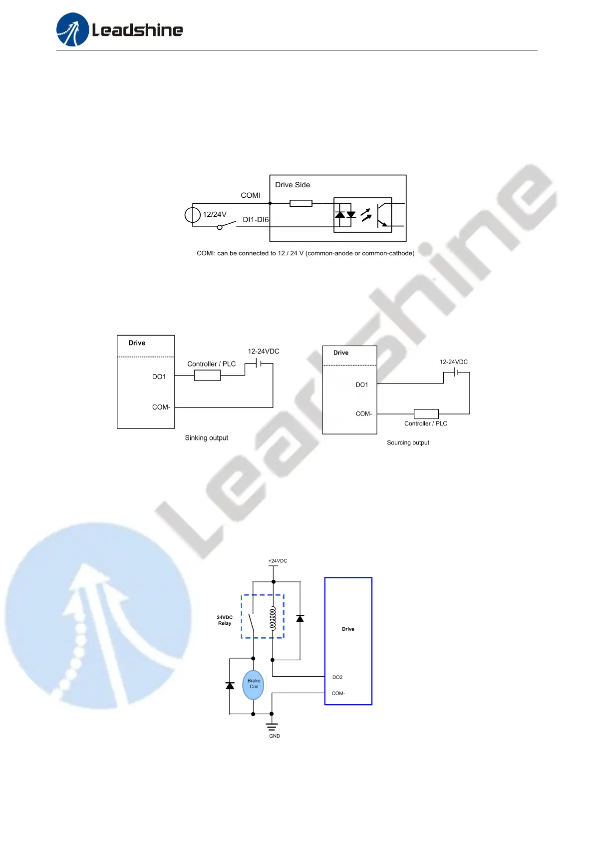
3.4 I/O Signals Wiring
3.4.1 Digital Input Wiring
Figure 3.4: Input Interface Connection
Note:
(1) Controller/PLC/Control card should provide input DC power 12-24V,current ≥ 100mA.
(2) If the polarity of input DC power is reversed, the EtherCAT Closed Loop stepper drive won’t work; you need to turn the wiring.
3.4.2 Digital Output Wiring
Figure 3.5: Output Interface Wiring
Note:
(1) The power supply (12-24VDC) above is provided by user,and if the polarity of power supply is reversed,it will damage the drive.
(2) Digital output is OC output with the maximum capacity of 100mA/30V (recommended 50mA/25V), the provided power supply
should be under 30V (recommended 24V),otherwise it will cause damage to the drive.
3.4.3 Brake Output Wiring
This driver has a special brake output, built-in a fly-wheel diode, driving current up to 500 mA, can directly
drive the motor brake without relays. The connection is below:
Figure 3.6: Brake output connection