SMC6000 Series Motion Controller Hardware Installation Manual
19
HWMN-SMC6-R20120417
The expansion I/O of Leadshine SMC6000 is connected to connector X1 of terminal board ACC37-7480 through a
cable with DB37 connector. The connector J2 pin assignment of ACC37-7480 is shown in table 3-1. The connector
J3 pin assignment of ACC37-7480 is shown in table 3-2. The interface circuit of those inputs and outputs in
ACC37-7480 are shown in figure 3-15 and figure 3-16, respectively.
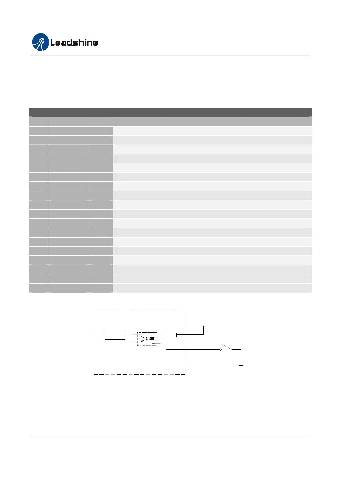
Table 3-1 Terminal Board ACC37-7480 General Purpose Input Connector J2 Pin Assignment
Terminal Board ACC37-7480 Connector J2 Pin Assignment
Pin Name I/O Description
1
IN1 I Expansion General-purpose Digital Input 17
2
IN2 I Expansion General -purpose Digital input 18
3
IN3 I Expansion General-purpose Digital Input 19
4
IN4 I Expansion General-purpose Digital Input 20
5
IN5 I Expansion General-purpose Digital Input 21
6
IN6 I Expansion General-purpose Digital Input 22
7
IN7 I Expansion General-purpose Digital Input 23
8
IN8 I Expansion General-purpose Digital Input 24
9
IN9 I Expansion General-purpose Digital Input 25
10
IN10 I Expansion General-purpose Digital Input 26
11
IN11 I Expansion General-purpose Digital Input 27
12
IN12 I Expansion General-purpose Digital Input 28
13
IN13 I Expansion General-purpose Digital Input 29
14
IN14 I Expansion General-purpose Digital Input 30
15
IN15 I Expansion General-purpose Digital Input 31
16
IN16 I Expansion General-purpose Digital Input 32
17
EGND GND External Power Ground
18
EGND GND External Power Ground
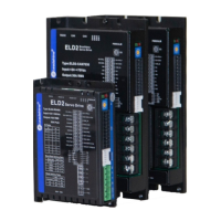
24V+
Switch
IN1(IN2~16)
Filter
Expansion I/O Terminal
Board ACC37-7480
EGND
Figure 3-15: Interface circuit of IN1~IN16 in terminal board ACC37-7480
Authorized Distributor of Leadshine Technology
www.leadtronker.com
www.leadtronker.com雷赛智能官方代理:雷创智能科技