2 ADJUSTMENT FOR OPERATION
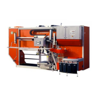
The POLYMAT W can be coupled behind a LELYTERRA or
directly behind a tractor.
The LELYTERRA needs to be fitted with the correct linkage
parts. See supplement C for the assembly and adjustment of
the linkage kit.
For individual operations of the POLYMAT, a special solo
hitch has to be fitted (see supplement C).
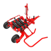
The position of the coulter beam in respect of the
POLYMAT’s main chassis is adjustable. This makes it
possible to set the coulter beam as shortly as possible behind
the LELYTERRA with any type of depth control roller for the
power harrow.
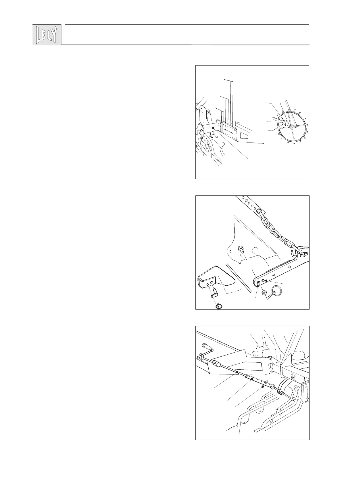
The position of the coulter beam can be adjusted as follows.
- Raise the POLYMAT until its wheels are only just clear of
the ground.
- Suspend a side frame A (fig. 3) in a hoist.
- Untighten the bolts of both side frames.
- Immobilize the side frames in a position whereby the
coulter beam remains clear of the LELYTERRA (a few
cm).
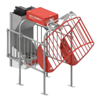
According to this method, the adjustment can be changed in
steps of 6 cm. When the free space between the coulter beam
and LELYTERRA amounts to something between 5 and 7,5
cm, the distance can be reduced by fitting the coupler arms
(fig. 4) and the lynch pin - use hole . This assembly allows
the side frames to be positioned 1 step further to the front.
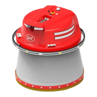
- Secure the chain casing of the metering wheel in any of the
positions I, II or III (fig. 3), in accordance with the position
of the side frames.
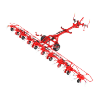
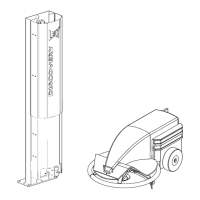
- Adjust the length of the spindle for coulter pressure setting
A (fig. 5) by means of the adjustment tube B and bolt
M6x35. Use the lowest hole if the lateral frames are fitted
in the rearmost position. If not, shift the bolt 1 position
upwards for each step by which the lateral frames are fitted
farther to the front.
- Make sure that the hoses always run downwards from the
hopper towards the coulters.
When the coulter beam has a forward position, those hoses
that are sagging need to be shortened.
(Shortening to be done only if adjustment of the coulter
beam to the rear is not likely.)
40
3
4
5
A
I
II
III
I
II
III
A
B
M6x35