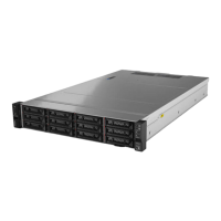
Table 3. Components on the front of server models
Callout Callout
1 VGA connector (optional)
2 Drive activity LED
3 Drive status LED
4 “Front I/O assembly with diagnostics panel” on page 8
5 Rack latch (right)
6 Pull-out information tab
7 Drive bays (12) 8 Rack latch (left)
Front IO assembly
The front IO assembly provides controls, connectors, and LEDs.
Figure 1. Front I/O assembly with diagnostics panel (on rack latch)
Table 4. Components on the front I/O assembly
Callout Callout
1 USB 3.0 connector 2 USB 2.0 connector with BMC management
3 Power button with power status LED
4 Network activity LED (for OCP 3.0 Ethernet adapter)
5 System ID button with system ID LED 6 System error LED
8 HR650X V2 User Guide
 Loading...