4.Locatetheheatsinkandfanassembly.See“Partsonthesystemboard”onpage7.
5.Disconnecttheheatsinkandfanassemblycablefromthemicroprocessorfanconnectoronthesystem
board.See“Partsonthesystemboard”onpage7.
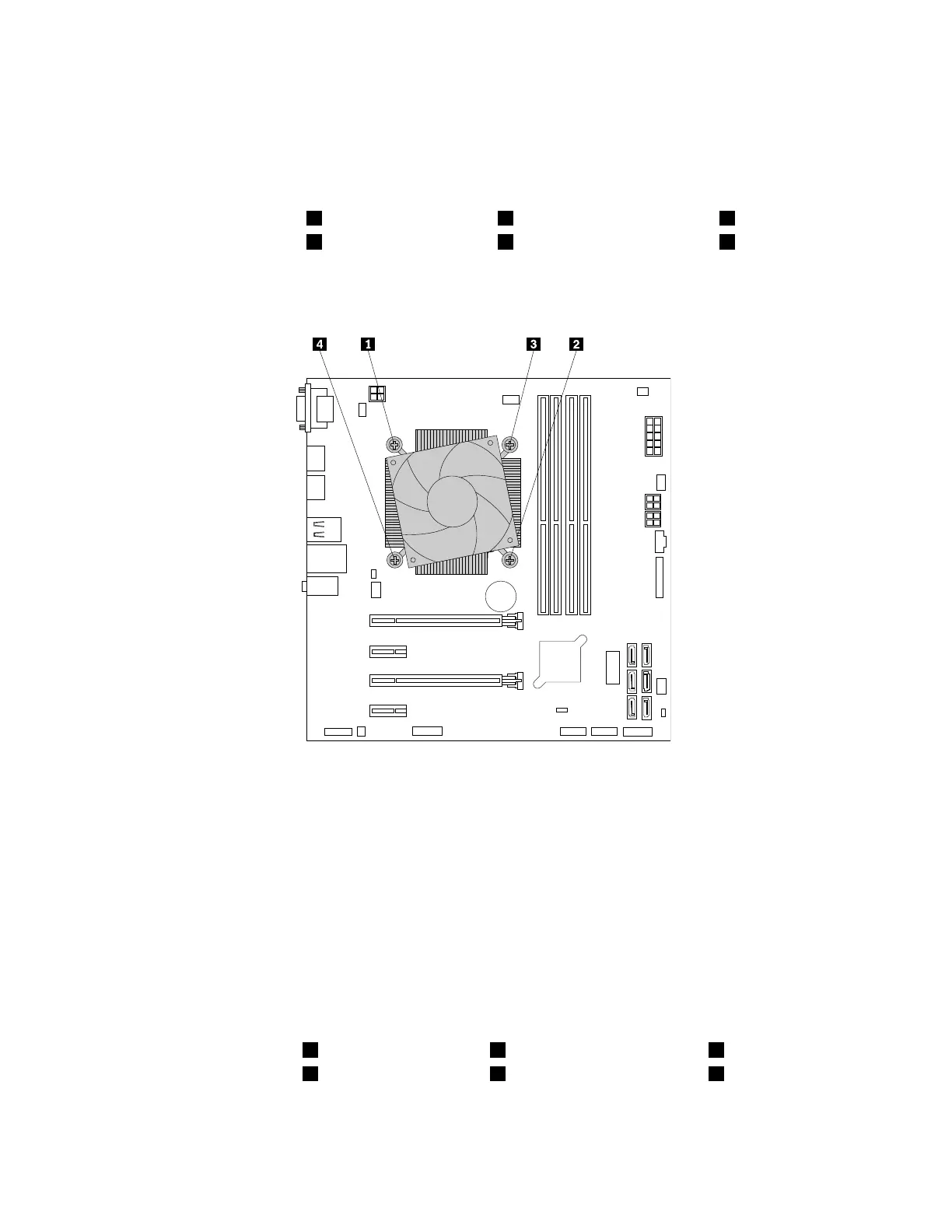
6.Followthefollowingsequencetoremovethefourscrewsthatsecuretheheatsinkandfanassembly
tothesystemboard:
a.Partiallyremovescrew1,thenfullyremovescrew2,andthenfullyremovescrew1.
b.Partiallyremovescrew3,thenfullyremovescrew4,andthenfullyremovescrew3.
Note:Carefullyremovethefourscrewstoavoidanypossibledamagetothesystemboard.Thefour
screwscannotberemovedfromtheheatsinkandfanassembly.
Figure59.Removingtheheatsinkandfanassembly
7.Liftthefailingheatsinkandfanassemblyoffthesystemboard.
Notes:
•Youmighthavetogentlytwisttheheatsinkandfanassemblytofreeitfromthemicroprocessor.
•Donottouchthethermalgreasewhilehandlingtheheatsinkandfanassembly.
8.Positionthenewheatsinkandfanassemblyonthesystemboard.Ensurethefourscrewsarealigned
withtheholesinthesystemboard.
Note:Ensurethattheheatsinkandfanassemblycableistowardthemicroprocessorfanconnector
onthesystemboard.
9.Followthefollowingsequencetoinstallthefourscrewstosecurethenewheatsinkandfanassembly.
Donotover-tightenthescrews.
a.Partiallytightenscrew1,thenfullytightenscrew2,andthenfullytightenscrew1.
b.Partiallytightenscrew3,thenfullytightenscrew4,andthenfullytightenscrew3.
10.Connecttheheatsinkandfanassemblycabletothemicroprocessorfanconnectoronthesystem
board.See“Partsonthesystemboard”onpage7.
86ThinkStationP310UserGuide