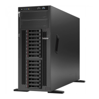
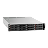
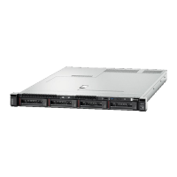
Figure 2. Front view of models with 12 drive bays
Table 2. Components on the front of the system (without bezel)
1 Chassis power LED 2 Chassis attention LED (front)
3 Chassis location LED (front) 4 Shelf ID digital display
5 Shelf ID change button 6 Hot-swap drive bays (12)
7 Drive activity LED 8 Drive status LED
2.2. Rear view
The rear of the system provides access to several connectors and components,
including the power supplies and various connectors. .Rear view
Table 3. Components on the rear of the system
1 RJ45 management ports (2) 2 RJ45 console ports (2) 3 USB-C console ports (2)
4 Storage host ports (2) 5 MiniSAS HD ports (6) 6 SFP28 Ethernet ports (4)
7 Host I/O ports (8) 8 Power supplies (2) 9 Power supply switches (2)
2.3. Rear view LEDs
The rear of the system provides system LEDs.
5

 Loading...


