Wiring of the standard device
Wiring of the system bus (CAN)
5
5.6
5.6−1
EDSVF9383V EN 6.0−11/2009
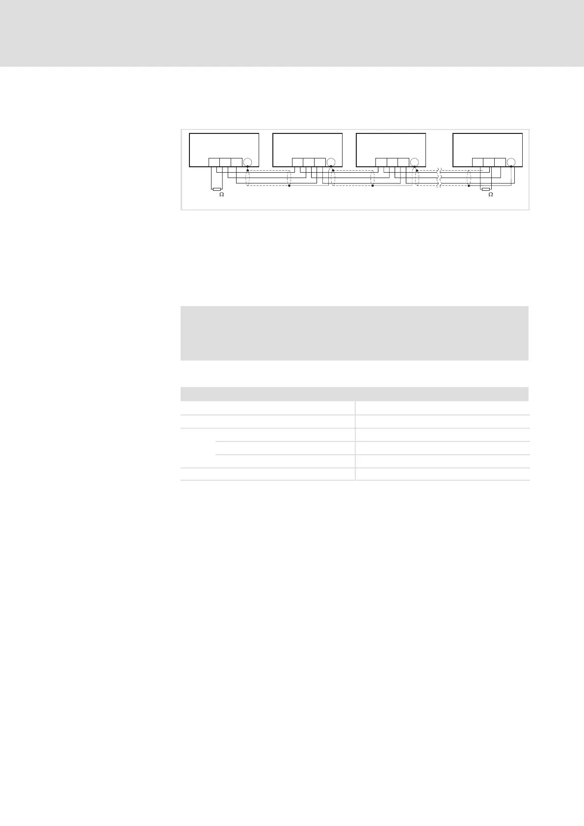
5.6 Wiring of the system bus (CAN)
A
1
A
2
A
3
A
n
93XX 93XX 93XX
GND GND GND GNDLO LO LO LOHI HI HI HIX4 X4 X4PE PE PE PE
120 120
9300VEC054
Fig. 5.6−1 System bus (CAN) wiring
A
1
Bus device 1 (controller)
A
2
Bus device 2 (controller)
A
3
Bus device 3 (controller)
A
n
Bus device n (e. g. PLC), n = max. 63
X4/GND CAN−GND: System bus reference potential
X4/LO CAN−LOW: System bus LOW (data line)
X4/HI CAN−HIGH: System bus HIGH (data line)
Stop!
Connect a 120 W terminating resistor to the first and last bus
device.
We recommend the use of CAN cables according to ISO 11898−2:
CAN cable according to ISO 11898−2
Cable type Twisted pair with shielding
Impedance 120 W (95 ... 140 W)
Cable resistance
Cable length £ 300 m £ 70 mW/m
Cable length £ 1000 m £ 40 mW/m
Signal propagation delay £ 5 ns/m
Wiring
efesotomasyon.com - Lenze