Technical data
Protective insulation
4
l
15
EDS82ZAFPC201 EN 4.0
4.3 Protective insulation
{ Danger!
Dangerous electrical voltage
If Lenze controllers are used on a phase earthed mains with a rated mains
voltage ³ 400 V, protection against accidental contact is not ensured without
implementing external measures.
Possible consequences:
ƒ Death or serious injury
Protective measures:
ƒ If protection against accidental contact is required for the control terminals
of the controller and the connections of the plugged device modules, ...
– a double isolating distance must exist.
– the components to be connected must be provided with the second
isolating distance.
Protective insulation between bus and ... Insulation type (acc. to EN 61800−5−1)
l Power section
– 8200 vector Reinforced insulation
– 8200 motec Reinforced insulation
– starttec Reinforced insulation
l Reference earth / PE (X3.1/7, X3.2/7) Functional insulation
l External supply (X3.1/59, X3.2/59) Functional insulation
l Terminal X3.1/E1, X3.1/E2 Functional insulation
l Terminal X3.1/20, X3.2/20 Functional insulation
l Terminal X3.2/28 Functional insulation
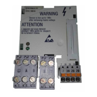
4.4 Connection terminals
Terminal
X3.1/
Designation Function / level
E1
Digital inputs *)
Adapt the individual setting via C0007 or C0410.
l Input resistance: 3.3 kW
l 0 = LOW (0 ... +3 V DC) PLC level, HTL
l 1 = HIGH (+12 ... +30 V DC) PLC level, HTL
(reference: GND2)
E2
20 DC voltage source for the internal supply of the digital inputs E1 and E2
l +20 V DC (reference: GND1)
l I
max
= 20 mA
39 GND2 Reference potential of the
l digital inputs at X3.1/E1 and X3.1/E2
l controller inhibit (CINH) at X3.2/28
59 External DC voltage supply for the function module
l +24VDC±10% (reference: GND1)
l Current consumption on 24 V DC: 80 mA
The current for looping through the supply voltage to other nodes via
terminal 59 must be max. 3A.
7 GND1 Reference potential for X3.1/20 and X3.2/20
*) Alternatively frequency input 0 ... 10 kHz (one−track) or 0...1kHz (two−track) configuration via C0425
 Loading...
