Commissioning
Activating the bus terminating resistor
Setting via code
6
l
33
EDS82ZAFPC201 EN 4.0
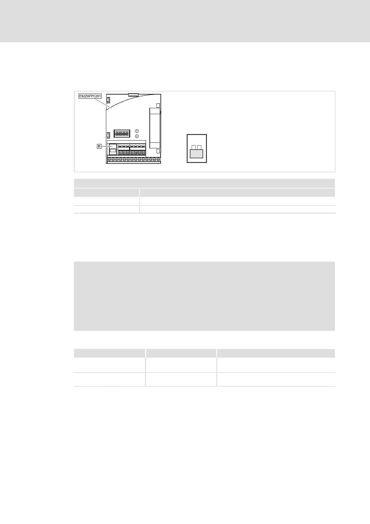
6.5 Activating the bus terminating resistor
The integrated bus terminating resistor can be activated with the DIP switch 3.
ON
E82ZAFP020B / E82ZAFP010
DIP switch 3
Switch position Function
OFF Bus terminating resistor not active.
ON Bus terminating resistor active.
6.6 Setting the node address
The bus device address can be set with the DIP switches S1 ... S7 (2) or via code C1509.
) Note!
ƒ The bus device addresses of networked controllers must differ from each
other.
ƒ If the DIP switches S1 ... S7 are in the OFF position, the code setting for the
bus device address is active.
ƒ Switch off the voltage supply of the function module and the controller, and
then switch it on again to activate changed settings.
Valid address range
Input via Valid address range Notes
l Operating module or
»GDC«
3 ... 126 −
l DIP switches 3 ... 125 If the addresses 0, 1, 2, 126 or 127 are set, the
settings from code C1509 become active.
6.6.1 Setting via code
ƒ DIP switches S1 ... S7 = OFF (Lenze setting)
ƒ Set the bus device address via C1509.