Configuration
Function blocks
Master frequency input (DFIN)
8
8.2
8.2.2
8.2-5
EDSVF9333V EN 3.0-06/2005
8.2.2 Master frequency input (DFIN)
The function block calculates a speed signal from the rectangular signals at
X9. TTL signals and HTL signals can be connected. The zero track can be
selected as an option.
The edge changes are d etected every 1 ms and result directly in the output
value.
C0425
C0427
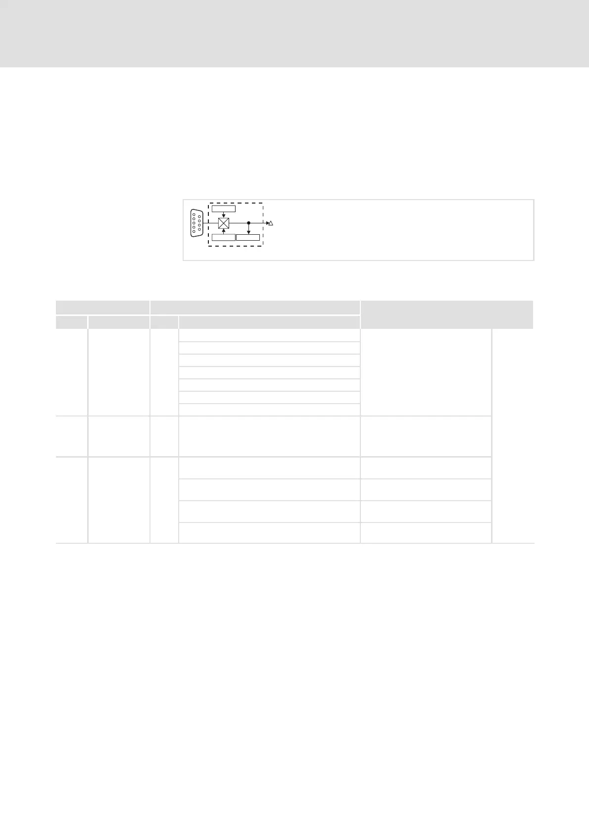
DFIN
DFIN-OUT
C0426
X9
fb_dfin
Fig. 8.2-2 Digital frequency input (DFIN)
Codes for parameter setting
Code Possible settings IMPORTANT
No. Name Lenze Selection
C0425 DFIN const 3
0 256 inc/rev
Constant of the master frequency
input, function block DFIN
z Output signal at the connected
encoderorattheupstream
controller in the event of a
master frequency
cascade/master frequency bus
8.2-5
1 512 inc/rev
2 1024 inc/rev
3 2048 inc/rev
4 4096 inc/rev
5 8192 inc/rev
6 16384 inc/rev
C0426 DIS: OUT -36000 {1 rpm} 36000 Output signal of the master
frequency input, function block
DFIN
z Display only
C0427 DFIN function 0
Function of the master frequency
input, function block DFIN
0 2-phase z Phase-displaced signal
sequence
1 Apulse/Bdir z Control of direction of rotation
via track B
2 Pulse A or B z Control of speed and direction
of rotation via track A or track B
Description