Multi−axis controllers
Device description
Devices in the range 2 ... 32 A (0.37 ... 15 kW)
4
189
EDS94SPP101 EN 10.2
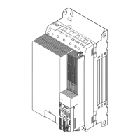
Standard device
Pos. Description
MXI1 Module receptacle for extension 1, e.g. communication
MXI2 Module receptacle for extension 2, e.g. communication
MMI Module receptacle for memory modules
MSI Module receptacle for safety equipment
X1 System bus (CAN), under the cover
X2 24 V supply and statebus
X3 Analog inputs and analog outputs
X4 Digital outputs
X5 Digital inputs
X6 Diagnostics
X7 Resolver
X8 Encoder
Lower cover
Retractable nameplate
Upper cover
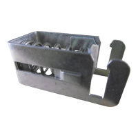
EMC clip
Prominent warning label close to the device!
The LED display enables fast indication of several operating states.
LED Labelling Colour Description
CAN−RUN green CAN bus ok
CAN−ERR red CAN bus error
DRIVE READY green Standard device is ready for operation
DRIVE ERROR red Error in the standard device or application−induced
24 V green 24 V supply voltage ok
SSP94LED01
USER yellow Message parameterised by the application
Pos. Symbol Description
Long discharge time: All power terminals carry hazardous electrical voltages
for a longer period of time after mains disconnection! Depending on the
device, this period of time may be up to 30 minutes.
High discharge current: Carry out fixed installation and PE connection
according to EN 61800−5−1!
Electrostatic sensitive devices: Before working on the device, the personnel
must be free of electrostatic charge!
Installation backplane
Pos. Description
X100 DC−bus voltage (compatible to 9300 series)
X105 Motor
X106 Motor temperature monitoring
X107 Control of motor holding brake
X109 DC busbar +
X110 DC busbar −
EMC wire clamp (for device sizes 2 + 3), replaces 1 x
EMC shield clamp
DC−bus fuse

 Loading...


