Power supply modules
Wiring
Devices in the range 10 ... 36 A (4 ... 18 kW)
5
272
EDS94SPP101 EN 10.2
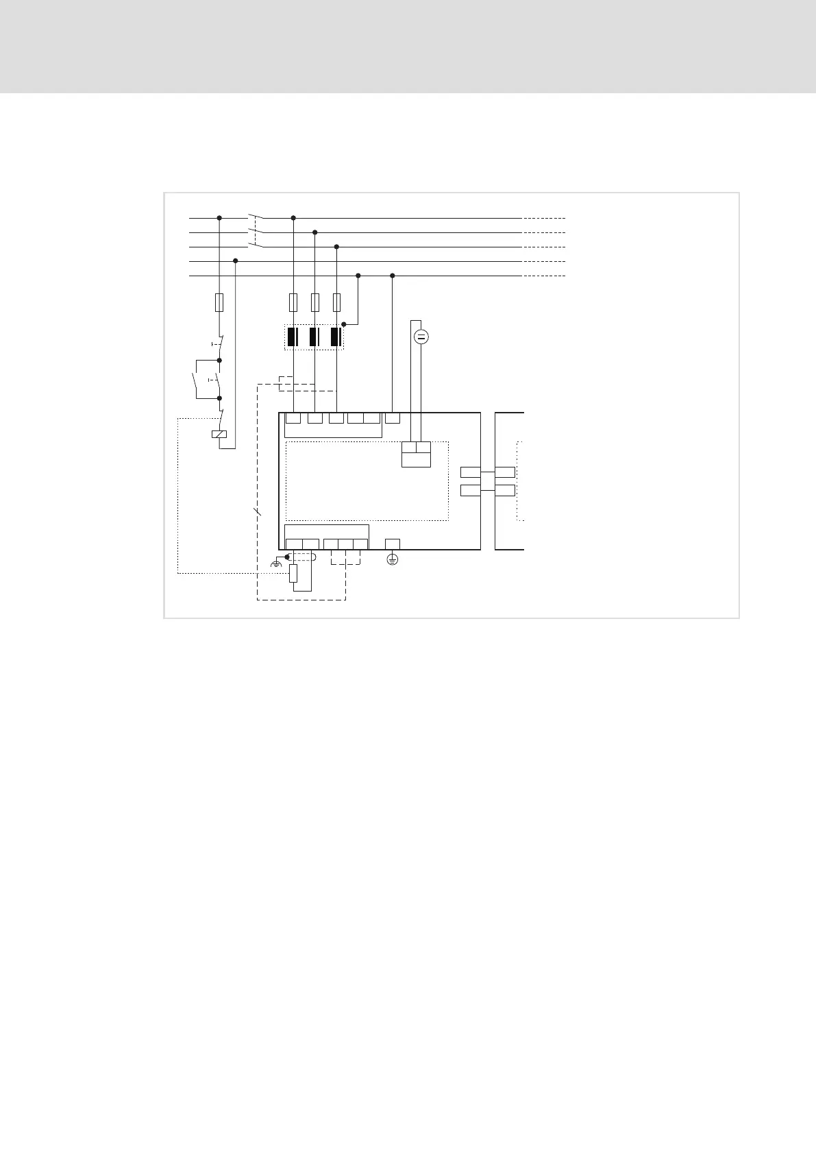
5.6.4 Devices in the range 10 ... 36 A (4 ... 18 kW)
Example circuit
3
L3
N
PE
L1
L2
F1...F3
R
B
E94AxxExxxx
E94AZPxxxxx
X109
X110
Z1
E94APNE0xx4
24E
GE
X11
E94AZPPxxxx
X109
X110
L1
L2
L3
X111
+UG -UG
L1
L2
L3
X112
Rb1 Rb2
K1
F4
K1
K1
O
I
R
B
J
+
-
?
+
+
SSP94PSP21
Fig. 5−5 Example circuit for installation backplane and DC power supply module
E94APNExxx4 9400 DC power supply module
E94AZPxxxxx Installation backplane
E94AxxExxxx 9400 axis module
E94AZEX100 DC input module
F1 ... Fx Fuses
Z1 Mains filter/RFI filter (optional)
K1 Mains contactor
RB Brake resistor
Alternative: mains connection at the bottom
24 V supply voltage for control electronics according to IEC 61131−2
Tip!
Complete the wiring of the installation backplane before plugging in the
standard device. The upper terminals of the installation backplane cannot be
connected with a plugged−in standard device.

 Loading...


