Power supply modules
Mechanical installation
Devices in the range 10 ... 36 A (4 ... 18 kW)
5
259
EDS94SPP101 EN 10.2
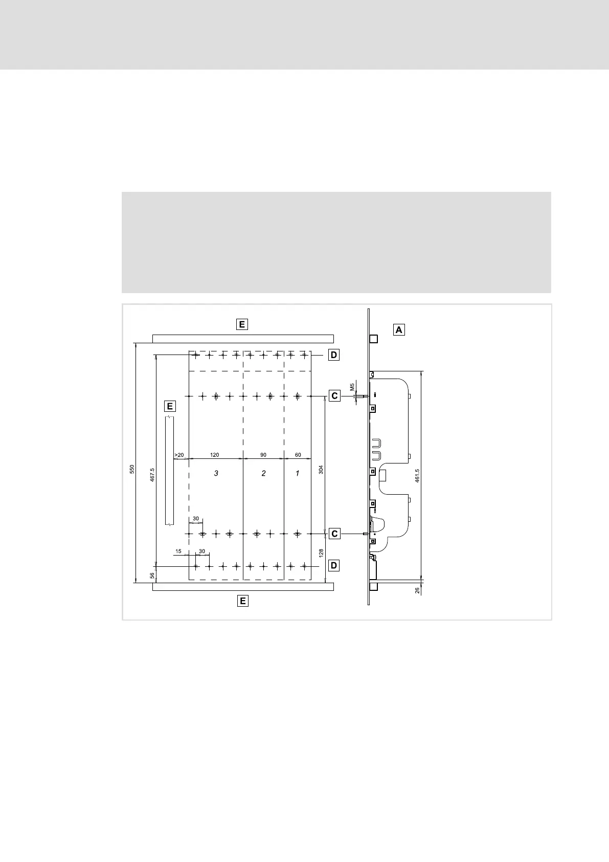
5.5.2 Devices in the range 10 ... 36 A (4 ... 18 kW)
Mounting grid
We recommend to provide the mounting plate with a grid pattern of M5 threaded holes
for attaching the devices. This preparation enables easy attachment of the devices, and the
device sizes 1, 2, ... n can thus be mounted directly adjacent to each other.
Note!
ƒ M5 screw and washer assemblies or hexagon socket screws with washers
are permitted.
ƒ Tightening torque: 3.4 Nm / 30 lb−in.
ƒ In the installation backplane, the screwed connection may not jut out more
than 7 mm.
SSP94PN010
Mounting with backplane for attaching the power supply module
Grid hole pattern for installation backplane
Grid hole pattern for other device sizes or built−on/footprint filters (only Single Drive)
Cable duct
1
...
3
Device size, mounting holes used

 Loading...


