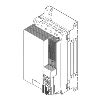
Multi−axis controllers
Mechanical installation
Devices in the range 2 ... 32 A (0.37 ... 15 kW)
4
196
EDS94SPP101 EN 10.2
Installation steps
E94AZJA−003
Proceed as follows for installation:
1. Prepare M5 threaded holes on the mounting plate according to the mounting grid.
– Start on the left with the mounting backplane of the E94AZPNxxxx DC power
supply module or with the E94AZEX100 DC input module.
– Install the axis modules from the left to the right with decreasing rated power.
– Axis modules E94AMxE0324 and installation backplane E94AZPM0324 can only be
connected directly to each other! A use with another device or installation
backplane of size 3 is not permissible and is prevented through a plug protection.
2. Screw the mounting backplane onto the mounting plate. Do not yet tighten the
screws.
– Use M5 screw and washer assemblies or M5 hexagon socket screws with washers.
– The screw joint in the installation backplane must not jut out more than 7 mm.
3. Align all components.
4. When busbars are used: connect busbars.
5. Screw the components onto the mounting plate.
– Tightening torque: 3.4 Nm (30 lb−in).

 Loading...


