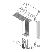
Power supply modules
Device description
Devices in the range 10 ... 36 A (4 ... 18 kW)
5
255
EDS94SPP101 EN 10.2
Standard device
Pos. Description
X11 24 V supply
X12
4 digital outputs
1 digital input
Nameplate, retractable
Setting of mains voltage/brake chopper threshold
Upper cap
The LED display enables fast indication of several operating states.
LED labelling Colour Description
− − −
OVERHEAT red Overtemperature
MAINS green without function
BRCHOP FAIL red Short circuit in brake chopper
24 V green 24 V supply voltage o.k.
SSP94LED21
BRCHOP ON yellow Brake chopper active
Pos. Symbol Description
Long discharge time: All power terminals carry hazardous electrical voltages
for a longer period of time after mains disconnection! Depending on the
device, this period of time may be up to 30 minutes.
High discharge current: Carry out fixed installation and PE connection
according to EN 61800−5−1!
Electrostatic sensitive devices: Before working on the device, the personnel
must be free of electrostatic charge!
Installation backplane
Pos. Description
X111
Mains (supply from above, e.g. from top filters)
DC−bus voltage (compatible with 9300 series)
X112
Mains (supply from below, e.g. from built−on filter)
External brake resistor
X109 DC−bus busbar +
Direct connection of
9400 axis modules,
device sizes 1 ... 3
X110 DC busbar −
EMC shield clamp

 Loading...


