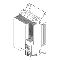
Power supply modules
Wiring
Devices in the range 100 ... 245 A (48 ... 119 kW)
5
277
EDS94SPP101 EN 10.2
Connecting busbars
SSP94PN401
Fig. 5−8 Example: Connecting busbars
Proceed as follows to connect the busbars:
1. If devices of the interconnected system have already been in operation:
– If necessary, switch off the supply system and wait until the discharge time has
elapsed (depending on the device, this may take up to 30 minutes).
– Make sure that all power terminals are deenergised.
2. Loosen the busbar screws (do not remove them completely).
3. Push the busbars as far as possible to the left towards the adjacent busbar.
– Ensure that there is good contact to the adjacent busbar.
4. Tighten the busbar screws.
– Tightening torque: 3.2 ... 3.5 Nm (28 ... 31 lb−in).
5. Screw the components onto the mounting plate, if necessary.
– Tightening torque: 3.4 Nm (30 lb−in).
The wiring area of the power terminals is designed for the cables being routed upwards

 Loading...


