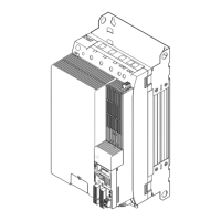
Accessories (overview)
Communication modules
INTERBUS
8
408
EDS94SPP101 EN 10.2
Connections
The INTERBUS is connected to the communication module by means of X206 (input, 9−pin
Sub−D connector) and X207 (output, 9−pin Sub−D socket).
E94YCIB001C
Assignment of the 9−pin Sub−D connector X206 (IN)
Pin Designation Input/Output Description
1 DO1 Input RS485: DO1 not inverted
2 DI1 Output RS485: DI1 not inverted
3 GND Reference potential
4 free not assigned
5 Vcc5 Output 5 V DC
6 /DO1 Input RS485: DO1 inverted
7 /DI1 Output RS485: DI1 inverted
8 Vcc5 Output 5 V DC
9 free not assigned
Assignment of the 9−pin Sub−D socket X207 (OUT)
Pin Designation Input/Output Description
1 DO2 Output RS485: DO2 not inverted
2 DI2 Input RS485: DI2 not inverted
3
GND
Reference potential
4
GND
5 Vcc5 Output 5 V DC
6 /DO2 Output RS485: DO2 inverted
7 /DI2 Input RS485: DI2 inverted
8 Vcc5 Output 5 V DC
9 RBST Signal input Connection to outgoing INTERBUS plugged in.

 Loading...


