Page 42
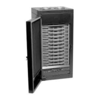
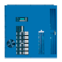
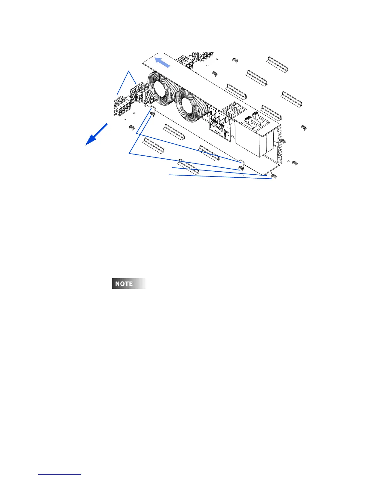
Figure 28 - Dimmer Module Installation and Removal
3 Slide the dimmer until the back of it slides underneath the tabs.
4 The dimmer should slide into the mating connector plugs with a small
amount of pressure.
The dimmer may need to be moved up and down or forward and
backward until the connectors mate. DO NOT FORCE.
5 Insert a #10-32 1/4-in. screw into the dimmer retaining hole to hold the
dimmer module in place. (Optional)
If the cabinet has been configured at the factory and there are
special dimmer modules, there will be a label indicating where
these modules should be placed. Verify that each module is
wired to the load as shown on these drawings. If the dimmer
modules are driving the wrong load circuits, damage can occur
to certain types of dimmer ballasts. Some ballasts are adversely
affected if the dimmed and switched connections are reversed.
Tab s
Retaining hole
Notches
D
i
m
m
e
r
m
o
d
u
l
e
Connector
plugs
Dimmer stop
s
lid
e
t
o
in
s
t
a
ll
Top Of Dimmer
Cabinet