300781172_002_C0 - 012/2019 - © Leybold 46
Options
3. Fit the connector.
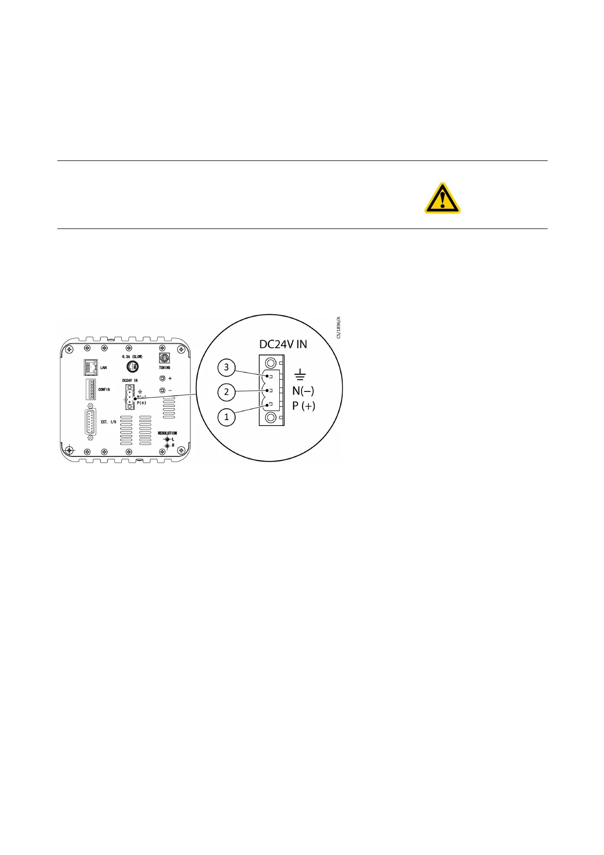
The pin assignment is shown in the dimensional drawing.
4. Plug in the power connector and tighten the screws securely so that the power
connector cannot detach.
5. Plug in the power supply. Always connect it to Class A ground.
Fig. 10.3 Sensor unit power supply connectors
CAUTION:
To prevent damage to the unit, make sure the power is off before making
connections.
1. +V (P (+) ) Positive polarity 24 V d.c. - white cable
2. -V (N (-) ) Negative polarity of 24 V d.c. - black cable
3. Frame GND ( ) Frame ground - green cable