13
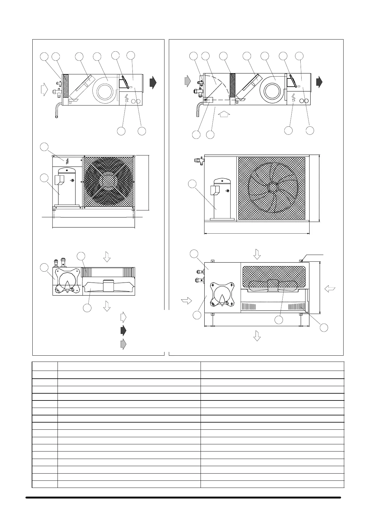
Fig. 8 --- Operation diagram --- Schema di funzionamento
Unit without freecooling
Unità senza freecooli ng
Unit with freecooling
Unità con freecooling
SIDE VIEW --- VISTA LATERALE
SIDE VIEW --- VISTA LATERALE
5 92 438
1
5
9
431
7
TOP VIEW --- VISTA DALL’ALTO
F R O N T A L V I E W --- V I S T A F R O N T A L E
11
6
10
11 10
6
SC 05--06
AIR FLOW
FLUSSO ARIA
AIR FLOW
FLUSSO ARIA
AIR FLOW
FLUSSO ARIA
AIR
FLOW
FLUSSO
ARIA
SC 08--10--13--14
conditioned air --- aria trattata
air return --- ripresa a ria
outside air --- aria esterna
690
1050
F R O N T A L V I E W --- V I S T A F R O N T A L E
TOP VIEW --- VISTA DALL’ALTO
526
887==
N. 4 x ø8
14
13
12
16
15
14
16
13
12
15
770
15
800
537
15
AIR FLOW
FLUSSO ARIA
AIR FLOW
FLUSSO ARIA
POS. DESCRIPTION DESCRIZIONE
1 Air return grille Griglia aspirazione aria
2 Freecooling damper (Freecooling version only) Serranda Freecooling (solo versione Fr eecooling)
3 Air filter Filtro aria
4 Evaporator coil Evaporatore
5 Evaporator unit f an Ventilatore unità evaporante
6 Air discharge duct Canale mandata aria
7 Damper motor (Freecooling version only) Motore serranda (solo versione Freecooling )
8 Air suction grille (Freecooling version only) Griglia ripresa aria di rinnovo (solo versione Freecooling)
9 Electric heaters (optional) Resistenze elettriche (opzionale)
10 Heater safety thermostat (heating version only) Termostato sicurezza resistenze (solo vers. riscaldamento)
11 Electrical panel evaporating unit Quadro elettrico unità evaporante
12 Condenser fan Ventilatore condensatore
13 Electrical panel condensing unit Quadro elettrico unità condensante
14 Refrigeration compressor Compressore
15 Variex Variex
16 Condenser coil Condensatore