Lighthouse ApexPortable Operating Manual
7-8 248083440-1 Rev 5
The Data Status flag is set if any of the channels have a threshold
exceeded state as true.
Note:
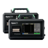
The
ApexPortable comes
standard with 4 particle
channels.
The threshold registers (45xxx series) shown in Table 7-8, run in
parallel with the data registers (30xxx series). For example, data
register 30010’s corresponding threshold register would be 45010. Data
register 30016’s threshold register would be 45016.
Setting the Alarm Threshold Value
The Alarm Threshold Value is set in the low register of the channels.
Each channel has independent threshold value registers. Since any or
all channels can be enabled for alarms at any given time, each threshold
value applies to the corresponding channel. Setting a value for channel
1 as 100 will not affect channel 2 setting of, say, 500. See Table 7-9.
Table 7-8 Alarm Threshold Registers
Register Data Type Description
45009 unsigned int Threshold for Particle Channel 1 [high]
(smallest particle size starts here)
45010 unsigned int Threshold for Particle Channel 1 [low]
45011 unsigned int Threshold for Particle Channel 2 [high]
45012 unsigned int Threshold for Particle Channel 2 [low]
45013 unsigned int Threshold for Particle Channel 3 [high]
45014 unsigned int Threshold for Particle Channel 3 [low]
45015 unsigned int Threshold for Particle Channel 4 [high]
45016 unsigned int Threshold for Particle Channel 4 [low]
Table 7-9 Alarm Threshold Registers set to 1000
Registers
Particle
Channel
Threshold
Value
45009 - 45010 1 1000
45011 - 45012 2 1000
45013 - 45014 3 1000
45015 - 45016 4 1000
 Loading...