THE BLUE BOX LT 1416 LT NSTALLATION GUIDE 119
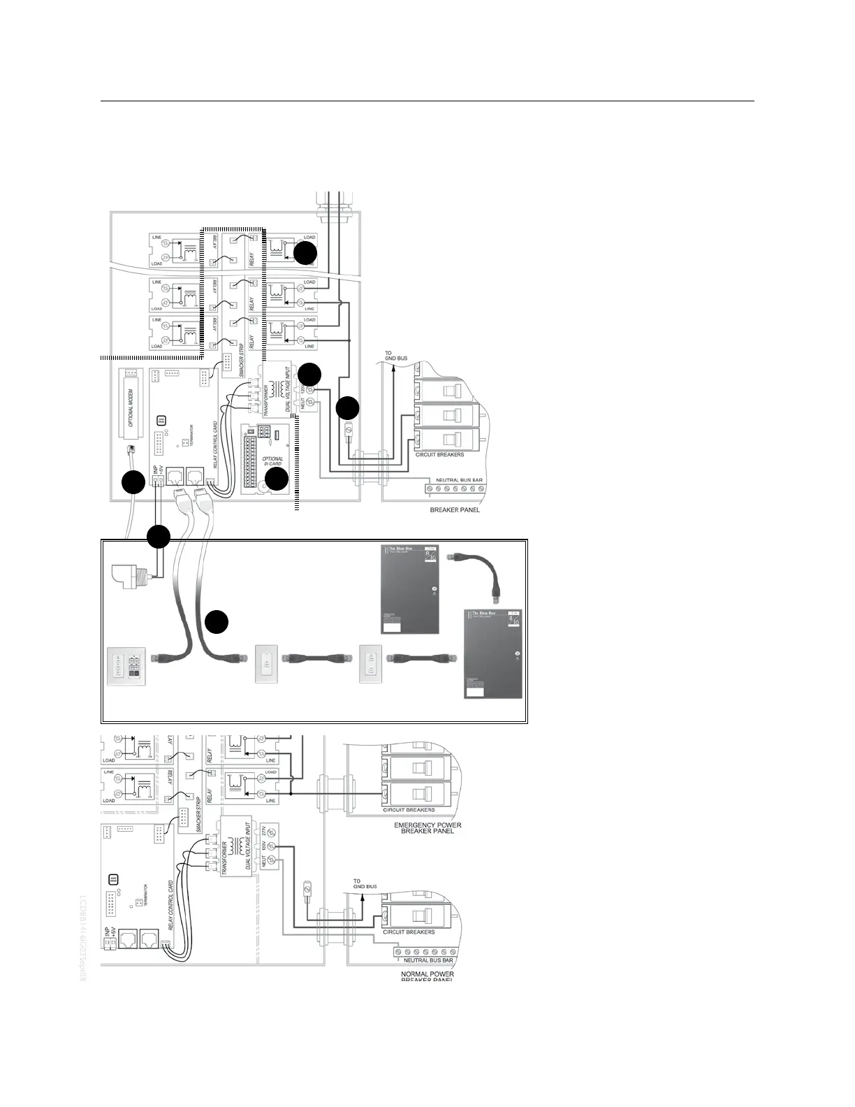
HOOk UP DIAGRAM
CONNECTIONS DETAILS
For internal wiring connections refer
to The Blue Box LT “O&M Manual”.
Relay lugs may hold up to 4#10 or 1.
2 #8 AWG. Neutrals may be run
through The Blue Box LT gutter.
Power supply lugs may hold up 2.
to 2#12. Use a dedicated power
supply breaker (see below for
controlling emergency loads).
Ground Lug - for grounding The 3.
Blue Box LT only.
2#18 AWG from photocell in-4.
put (master panel only) to out-
door photocell (up to 300 ft). If
longer, use shielded cable.
Cat. 5 from RJ45 sockets connect 5.
The Blue Box LT to other digital
devices (switches, relay panels,
etc.). Refer to “
System Start-Up
Cabling Guide”
when making
these connections, and before
powering-up The Blue Box LT.
Wiring details for optional Digi-6.
tal Input Card are shown on the
“DI Installation Guide.”
Run 4-conductor, flat cable from 7.
modem to an analog phone jack.
Refer “Modem Installation Guide.”
EMERGENCY LOADS
To switch emergency on in the event
of a loss of normal power, feed the
power supply with a dedicated nor-
mal-power breaker (left).
To hold relay status (on or off) in the
event of a loss of normal power, feed
The Blue Box power supply with a
dedicated emergency-power breaker
via a server-quality UPS (load is less
than 10 watts).
1
4
5
6
3
2
Chelsea Digital Switches
Slave Blue Box
Slave Blue Box
Outdoor
Photocell
7
 Loading...