64 THE BLUE BOX LT TROUBLESHOOTING WITH AN OSCILLOSCOPE
LCDBBTSWO03Sept08
USING AN OSCILLOSCOPE TO TEST
A DIGITAL BUS
In troubleshooting a system or a bus, the “Final Activation
Checklist” is always the first and most important step. An Os-
cilloscope is a visual aid to troubleshoot the bus better.
The Oscilloscope will let one test the stability of the bus
while everything is powered up. This will show if the bus
is getting noise, how clean the bus signal is, if the bus is
properly terminated, if there is a bad device present on
the bus, and give an indication of crimp quality.
Below are some examples where the use of an Oscillo-
scope is definitely needed:
The Hardware Activation Tests included the “System 1.
Startup and Cabling Guide” passed, but when the sys-
tem is powered up, devices appear/disappear on the
bus scan.
The Hardware Activation Tests passed, but some de-2.
vices don’t seem to be working if the bus is connect-
ed, and the same devices work perfectly fine when
connected directly to a master panel.
Everything else was checked (The Hardware Activa-3.
tion Tests” passed and all devices are good) but the
bus is still unstable.
HOW TO SETUP THE SCOPE FOR TESTING
Make sure the Oscilloscope is not earth grounded in any
way. A battery powered scope is best.
Connect the probe leads to the system’s A & B ter-1.
minals; A “Bus Checker Card” may be used to make
the testing easier. Attach the alligator clip (which is the
ground lead of the probe) to the bus checker card’s
B terminal, then connect the main probe lead (which
is usually a retractable hook tip) to the bus checker
card’s A terminal.
Adjust the vertical & horizontal controls accordingly 2.
and set the input coupling to DC. You should be able
to see your bus signal which is a “Square Wave Sig-
nal.”
The advisable setting would be “1.0 volts/div” & “(20 3.
µs to 50 µs) sec/div” this should be able to let one see
a decent size waveform on the screen. (10-1 Probe).
A completely “Stable Bus” should show a clean & bal-4.
anced square wave signal. The baseline is centered at
“0” and never changes.
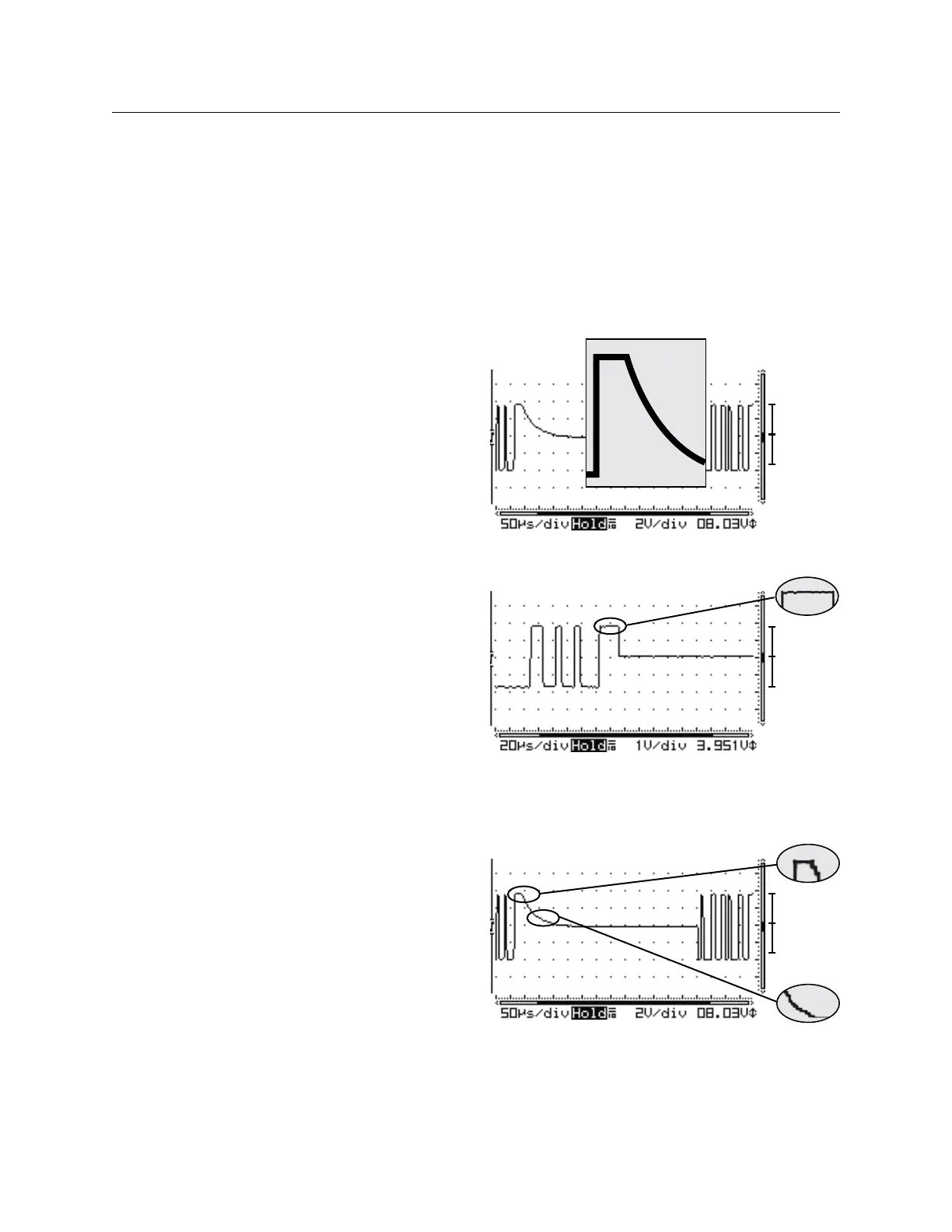
If the bus is not terminated properly, some “ringing” 5.
may be seen. With less loading, the Vpp is higher. If
there are not bad devices, the baseline is still at Zero.
+V = -V
+V = -V
Ideal wave form; Square waves with no ring or dampen-
ing means the bus is terminated. +V = -V means no bad
devices.
+V =
-
V
Problematic: Dampened square wave means the bus is
missing one or both terminators. +V = -V means no bad
devices.
 Loading...