THE BLUE BOX LT SYSTEM START-UP & CABLING GUIDE 99
SYSTEM ACTIvATION
AUTO ADDRESS DEvICES
Starting up a new system requires a few simple steps.
Consider the following steps to set-up and start the sys-
tem (see page 6 for DTC navigation).
1. After completing the Hardware Activation Tests, power
up all slave panels, and active devices (any device with
an onboard - 120 or 277 - power supply) first and then
power up the master panel. Check that the power-indi-
cator LEDs on all digital devices are lit-up.
2. The main screen will be displayed for a few seconds, af-
ter which the “device detection” screen will be displayed.
TAB to YES and ENTER to auto-address devices.
If the number of devices
detected do not match
the number of devices
present on the bus, pro-
ceed to trouble-shooting
section.
Found 1 device on the
system that are not used.
Would you like to
auto-assign them?
YES / NO / ->
Never Ask Again
4. To view address assignments in the “Serial Number
Scan” screen TAB to YES and ENTER.
The “Serial Number
Scan” screen displays the
serial number, address,
and device-type of added
device(s)
Assigned 1 device.
Review assignments by
scanning all serial
numbers?
YES / NO
FILL OUT SYSTEM DEvICE SCHEDULE
6.
I
n the “Serial#” field SCROLL to review each device
(including DI cards). If collisions are present or if two
devices share the same address, contact Tech Support.
SCAN BY SERIAL#
SERIAL# CE80
ADR: 1
Item Type: Switch
Mapd: 6 Btn. Switch
Address OK
SAVE ADDRESS CHANGES
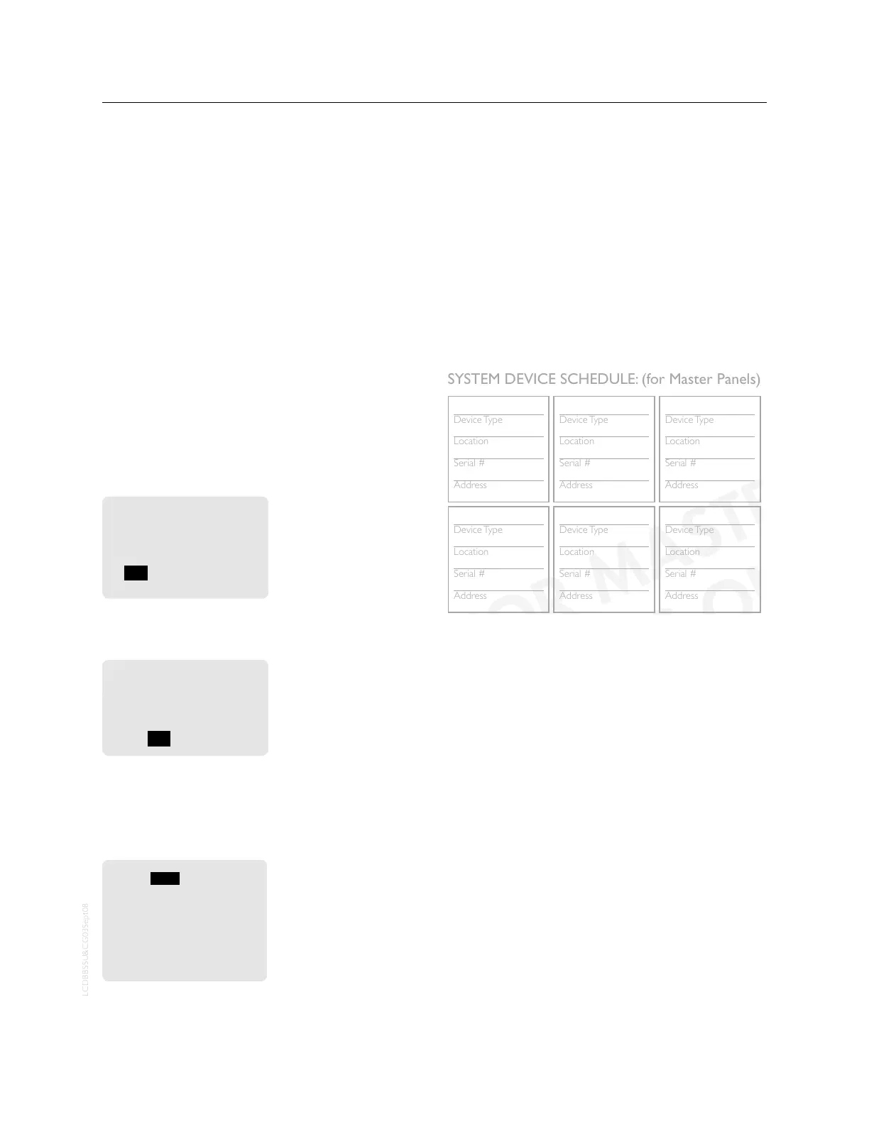
Fill out the “System Device Schedule” located on the back
of the “Panel Schedule” inside the master panel.
If unable to correlate the serial numbers and device loca-
tions when filling out the “System Device Schedule”, refer
to the serial label on each device or follow the “Read Ad-
dress” section of the Blue Box LT “O&M Manual”.
Device Type
Location
Serial #
Address
Device Type
Location
Serial #
Address
Device Type
Location
Serial #
Address
Device Type
Location
Serial #
Address
Device Type
Location
Serial #
Address
Device Type
Location
Serial #
Address
Device Type
Location
Serial #
Address
Device Type
Location
Serial #
Address
Device Type
Location
Serial #
Address
Device Type
Location
Serial #
Address
Device Type
Location
Serial #
Address
Device Type
Location
Serial #
Address
Device Type
Location
Serial #
Address
Device Type
Location
Serial #
Address
Device Type
Location
Serial #
Address
Device Type
Location
Serial #
Address
SYSTEM DEVICE SCHEDULE: (for Master Panels)
LIGHTING CONTROL & DESIGN
905 Allen Ave s Glendale, CA 91201s Support 800-345-4448 s www.lightingcontrols.com
(Master) LCP1
1
L
BB Panel Schedule.indd 4 8/13/2008 1:37:47 PM
3 btn sw
Hallway
8875
3
6 btn sw
lobby
4685
4
DI-6
LCP 1
4055
7
LCP 2
telecom
af97
5
(Master) LCP1
elec rm
ce80
1
ERROR CHECk
The system is now ready for Error Checking. Press EXIT
repeatedly to go back to the main menu.
7. Navigate to the “Error Statistics” screen. Use the path
USER MENU > SETUP MENU > RESTRICTED > AD-
DRESSING-BUS SCAN > ERROR STATISTICS. The
password to enter the RESTRICTED area is 900001.
8. TAB to the field that says CLEAR and press ENTER to
clear errors. If after 3 minutes no errors accumulate on
this screen, your system is stable.
9. If errors continue to accumulate refer to the Error
Check Troubleshooting section of the Blue Box LT
“O&M Manual” or call Technical Support for assistance
at 800-345-4448.
vERIFY DATE, TIME & LOCATION
To change the factory programmed settings, refer to the
Blue Box LT “O&M Manual”.
 Loading...