REMOVING THE ENGINE FROM TRACTOR
Proceed
according
to
the
following
sequence:
1.
i1emove the radiator
grill
after
removing
the
•Jpper
bolts
in
either
direction,
then
discon·
nect the battery cables and remove battery.
(See Fig. A.0/4.)
2.
Drain all fuel and
close
the fuel valve. Drain
the crankcase
oil
through
the
bottom
plug
hole and
the
crankcase and
radiator
coolant
through
the
plugs
(Items 13 and 14, Fig.
A.0/5)
located
on the
left
side
of
the
engine.
3 Remove the
front
axle
with
radiator,
after
disconnecting
or
detaching:
(a)
Transmission
oil
suction
line
(Item 21,
Fig. A.0/6)
to
hydraulic
pump
and
delivery line (Item
20)
to
hydraulic
lift;
making sure
to
plug
holes
to
prevent
spill·
age
of
oil
and
contamination
of
lines.
(b)
Band clamp
securing
air
cleaner
hose
(Item
19)
to
intake
manifold
water
inlet
and
outlet
hoses
from
radiator
and,
finally, the
exhaust
muffler
(Item
11);
(c)
Steering drag
link
(Item
12)
from steering
arm (if applicable).
(d)
Remove
bolts
holding
ram
anchor
to
transmission
housing.
Lock the parking brake.
Insert
two
wooden wedge
blocks
on the axle
and
lift
tractor
with
a hydraulic
jack
or
hoist
until
free from the engine; place
shop
stands
or
wooden
blocks
under
the
transmission
case, remove the
capscrews
(Item
C2,
Fig.
A.0/5)
attaching
axle
to
oil
sump
and, finally,
·remove the front axle
assembly
cowling
and
radiator.
A CAUTION:
When using
the
axle wedges, be sure
they
fit
and
are driven in
tight.
Also, any
blocks
or
stands
us·
ed
in
splitting
the
tractor
should
be stable. The
brakes
should
be
locked
by
stepping
on
the
brake pedals and
pulling
the
parking brake back.
Be sure any
slings
or
chains
are capable
of
sup-
porting
the
portion
of
the
tractor
to
be
hoisted.
4.
Remove
the
rear hood
section
with
instru·
ment and rear panels:
(a)
The
starting
and
lighting
switch
(Item 26,
Fig. A.0/7) and
the
starting
switch
(Item
30)
and lever.
(b) Remove
the
rear hood,
instrument
panel
and rear panel
attaching
capscrews;
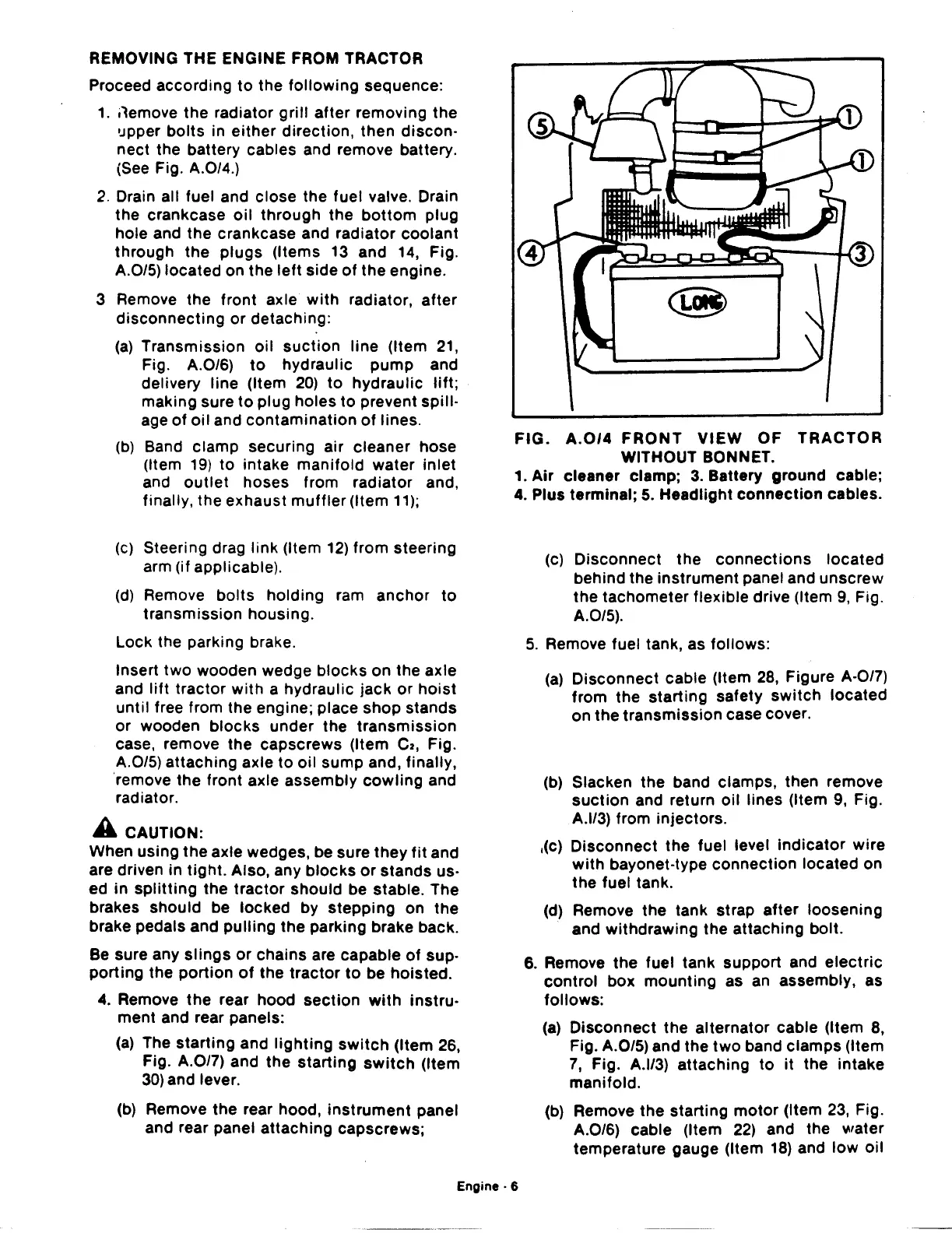
FIG.
A.0/4
FRONT
VIEW
OF
TRACTOR
WITHOUT BONNET.
1.
Air
cleaner clamp;
3.
Battery
ground
cable;
4. Plus terminal;
5.
Headlight
connection
cables.
(c)
Disconnect
the
connections
located
behind the
instrument
panel and
unscrew
the
tachometer flexible drive (Item
9,
Fig.
A.0/5).
5.
Remove fuel tank, as follows:
(a)
Disconnect
cable (Item
28,
Figure A·0/7)
from
the
starting
safety
switch
located
on
the
transmission
case cover.
(b)
Slacken the band clamps, then remove
suction
and return
oil
lines (Item
9,
Fig.
A.l/3) from injectors.
,(c)
Disconnect
the
fuel level
indicator
wire
with
bayonet-type
connection
located on
the fuel tank.
(d) Remove the tank strap
after
loosening
and
withdrawing
the attaching bolt.
6. Remove
the
fuel
tank
support
and
electric
control
box
mounting
as
an
assembly, as
follows:
(a)
Disconnect
the
alternator
cable (Item 8,
Fig. A.0/5) and the
two
band
clamps
(Item
7,
Fig. A.l/3)
attaching
to
it
the
intake
manifold.
(b) Remove
the
starting
motor
(Item 23, Fig.
A.0/6) cable (Item
22)
and the water
temperature gauge (Item
18)
and
low
oil
Engine·
6