B.VI FINAL DRIVES AND REAR WHEELS
25297
/
~~~
~--1
.
!),,
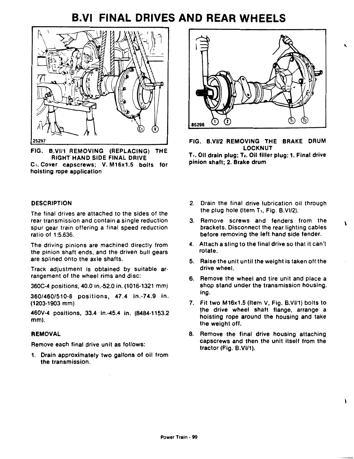
FIG. B.VI/1 REMOVING (REPLACING) THE
RIGHT HAND SIDE FINAL DRIVE
c,. Cover
capscrews;
V. M16x1.5
bolts
for
hoisting
rope
application
DESCRIPTION
The final drives are attached
to
the sides
of
the
rear transmission and contain a
single
reduction
spur gear train
offering
a final speed reduction
ratio
of
1:5.636.
The driving pinions are machined
directly
from
the pinion shaft ends, and the driven bull gears
are splined
onto
the axle shafts.
Track
adjustment
is obtained by suitable ar·
rangement
of
the wheel rims and disc:
360C-4 positions, 40.0 in.-52.0 in. (1016·1321 mm)
360/460/510-8
positions,
47.4
in.-74.9
in.
(1203-1903 mm)
460V-4
positions,
33.4 in.-45.4 in. (8484-1153.2
mm).
REMOVAL
Remove each final drive
unit
as
follows:
1.
Drain
approximately
two
gallons
of
oil
from
the
transmission.
85298
FIG. B.VI/2 REMOVING THE BRAKE DRUM
LOCKNUT
T,. Oil drain plug;
Tz.
Oil
filler
plug;
1.
Final drive
pinion
shaft;
2.
Brake
drum
2.
Drain the final drive lubrication oil through
the plug hole (Item T
,,
Fig. B.VI/2).
3.
Remove
screws
and fenders from
the
brackets.
Disconnect
the rear
lighting
cables
before removing
the
left
hand side fender.
4.
Attach
a
sling
to
the
final drive so
that
it
can't
rotate.
5.
Raise
the
unit
until
the
weight
is taken
off
the
drive wheel.
6. Remove the wheel and tire unit and place a
shop
stand
under
the
transmission
housing.
in
g.
7.
Fit
two
M16x1.5 (Item
V,
Fig. B.VI/1)
bolts
to
fhe drive wheel
shaft
flange, arrange a
hoisting
rope around the housing and take
the
weight
off.
8. Remove the
final
drive housing attaching
capscrews and then the
unit
itself
from the
tractor
(Fig. B.VI/1).
Power Train • 99
\