INJECTION PUMP
DESCRIPTION
Injection
pump maintains pressure
to
injectors.
To aid dependability, pump has been designed
to
eliminate failure- and wear-prone parts such as
gears and springs. Oiling is unnecessary -
pump housing contains fuel oil under pressure
to
prevent airlocks and keep
out
dust, water, and
particles
which
would reduce
efficiency
and
shorten service life.
Pump Is block-mounted, driven by a tapered
shaft
secured by a key, and revolves counter-
clockwise,
as seen from shaft end
of
pump.
Fuel enters
(48,
Fig. A.IV/8)
injection
pump,
passes through pressure-regulating valve in end
plate
(49),
through vane-type transfer pump
(25,
27,
28),
through metering valve
(42)
controlled by
throttle
arm
(36),
and
into
hollow shaft
of
rotor
(46).
Pumping pressure is applied
to
fuel by cam-
operated
pistons
(13).
Fuel then flows
to
distributor
ports
(47),
through outlet ports
(22)
to
.high-pressure connections
(21)
which feed high·
pressure lines
to
injectors.
Fuel
flow
is
controlled by a mechanical governor,
and
automatic
advance device, and by a
hydraulic damper
(97,
Fig. A.IV/7).
14023
NOTE: Overhauling
of
injection
pump
must
be
done only by authorized service personnel.
UNAUTHORIZED BREAKING OF SEALS
DUR-
ING WARRANTY PERIOD WILL VOID ENGINE
AND FUEL INJECTION SYSTEM WARRANTY.
Dealer service Is limited
to
replacement
of
exter·
nal seals and gaskets and adjustment
of
idle and
high
no-load speeds. Contact your LONG service
manager for assistance.
REMOVING INJECTION PUMP
1.
Remove injection pump drive-gear cover.
Disconnect high-pressure lines. Remove fuel
lines between
injection
pump and second
fuel
filter-cap
or
plug all openings.
2.
Disconnect control links
to
throttle arm
(36,
Fig. A.IV/8) and governor shut-off lever
(32).
3.
Back out center cap screw, which acts as a
puller to remove gear.
4.
Remove cap screws attaching injection
pump to timing-gear case, and remove injec-
tion
pump.
14023
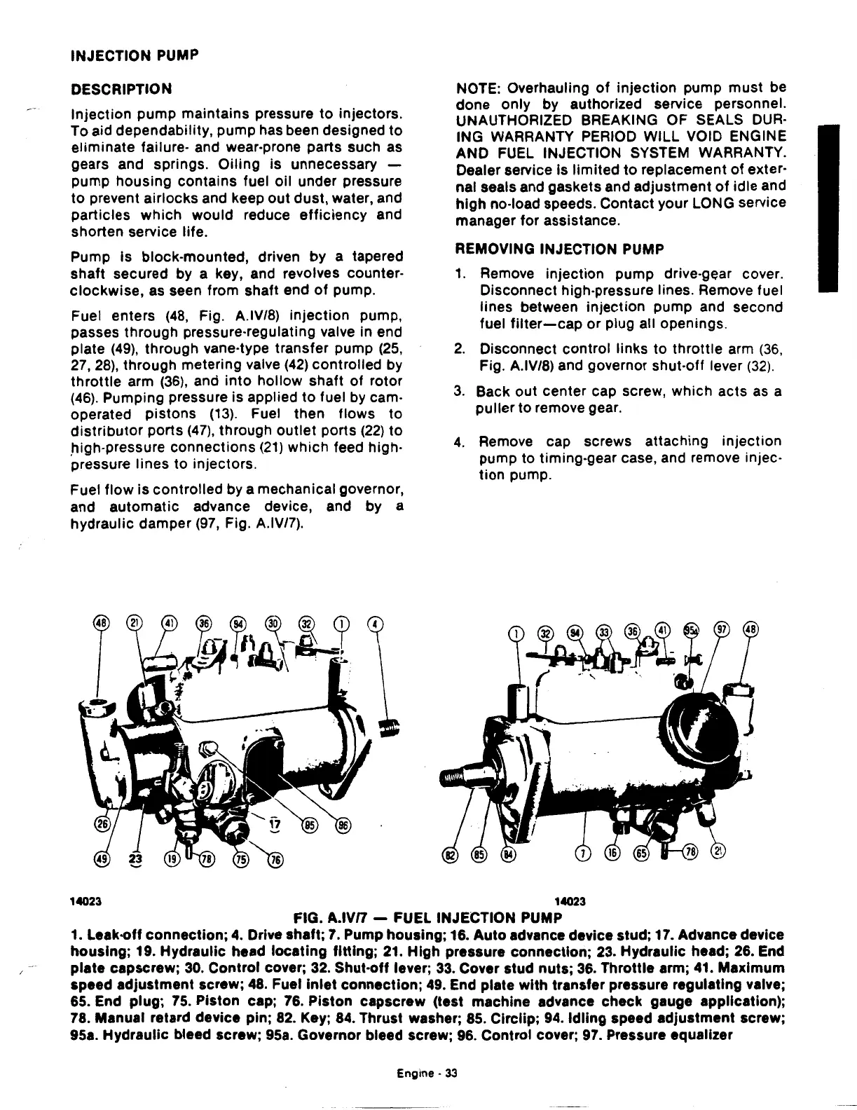
FIG.
A.IVn
- FUEL INJECTION PUMP
1. Leak·off
connection;
4.
Drive shaft;
7.
Pump housing; 16.
Auto
advance device stud; 17. Advance device
housing;
19. Hydraulic head locating
fitting;
21.
High
pressure connection; 23. Hydraulic head; 26. End
plate
capscrew;
30.
Control
cover; 32. Shut·off lever;
33.
Cover stud nuts; 36. Throttle arm; 41. Maximum
speed
adjustment
screw; 48. Fuel
inlet
connection; 49. End plate
with
transfer pressure regulating valve;
65. End plug;
75.
Piston cap; 76. Piston capscrew (test machine advance check gauge application);
78. Manual retard device pin; 82. Key; 84. Thrust washer; 85. Circlip;
94.
Idling
speed adjustment screw;
95a. Hydraulic bleed screw; 95a. Governor bleed screw; 96. Control cover; 97. Pressure equalizer
Engine·
33