INSPECTION
Checks required
for
the
10"
clutch
are as
follows:
1. Functional
efficiency
of
the
disc
friction
lin-
ings (Items
1 and 8, Fig.-8.1/5) and
conditions
of
mating
metallic
surfaces. The
latter
are
polished,
if
necessary. If the
discs
are im-
pregnated
with
oil
it
is
best
to
replace them,
as washing in solvent and
brushing
are
not
enough.
2.
The
friction
surfaces
of
the pressure plates
should be free from scoring
or
signs
of
ab-
normal wear, and if so
it
is
possible
to reface
them by
turning
them down on a lathe (see
"Fits
and
Tolerances"
table).
3.
The hubs of the driven plates should have no
play on the rivets.
4. The side clearance
of
the
disc
hub
splines
with the splined shafts.
5.
The
condition
of
the throw-out collar
thrust
beanng and of the
clutch
shaft
pilot
bearing
in the flywheel.
6.
Loading
spring
strain
values
versus
specifications
in
"Fits·
and Tolerances'"
table.
7. Sliding surface
conditions
of
throw-out
collar
and support. If wear is
still
within
limits.
the
support can be rotated
180
•,
and
if
not.
replace the parts
if
excessive play causes
grease leakage.
10"
CLUTCH ASSEMBLY
Prior
to
assembly, lubricate the
following
items
with
a film of lithium-base grease:
transmission
clutch
release lever pivots, the ball heads
of
the
clutch
release rods (mainly
to
hold them in place
at assembly), the
outer
surfaces
of
the forks
of
the pressure plates (Items 3 and
6.
Fig.
8.115)
and
the inside surface
of
the fork
locations
on the
clutch
cover (Item
10).
Assemble the
clutch
referring
to
the
following
notes:
1. Place the pressure plate (Item
3,
Fig.
8.1/5).
adjusting
screw (Item
7)
supporting
plate.
pressure plate (Item
6)
and
the
clutch
cover
(Item
10)
in
their
original
positions
arranging
them
with
their
assembly marks (scribed at
disassembly) in register.
2.
Install the
transmission
clutch
disc
(Item
8)
with
the
oil
slinger
away from the flywheel.
3.
Tighten the
attaching
cam
screws
(Item
C2,
Fig.
8.1/4)
to
the
torque value
specified
in the
"Torque
Specifications"
table.
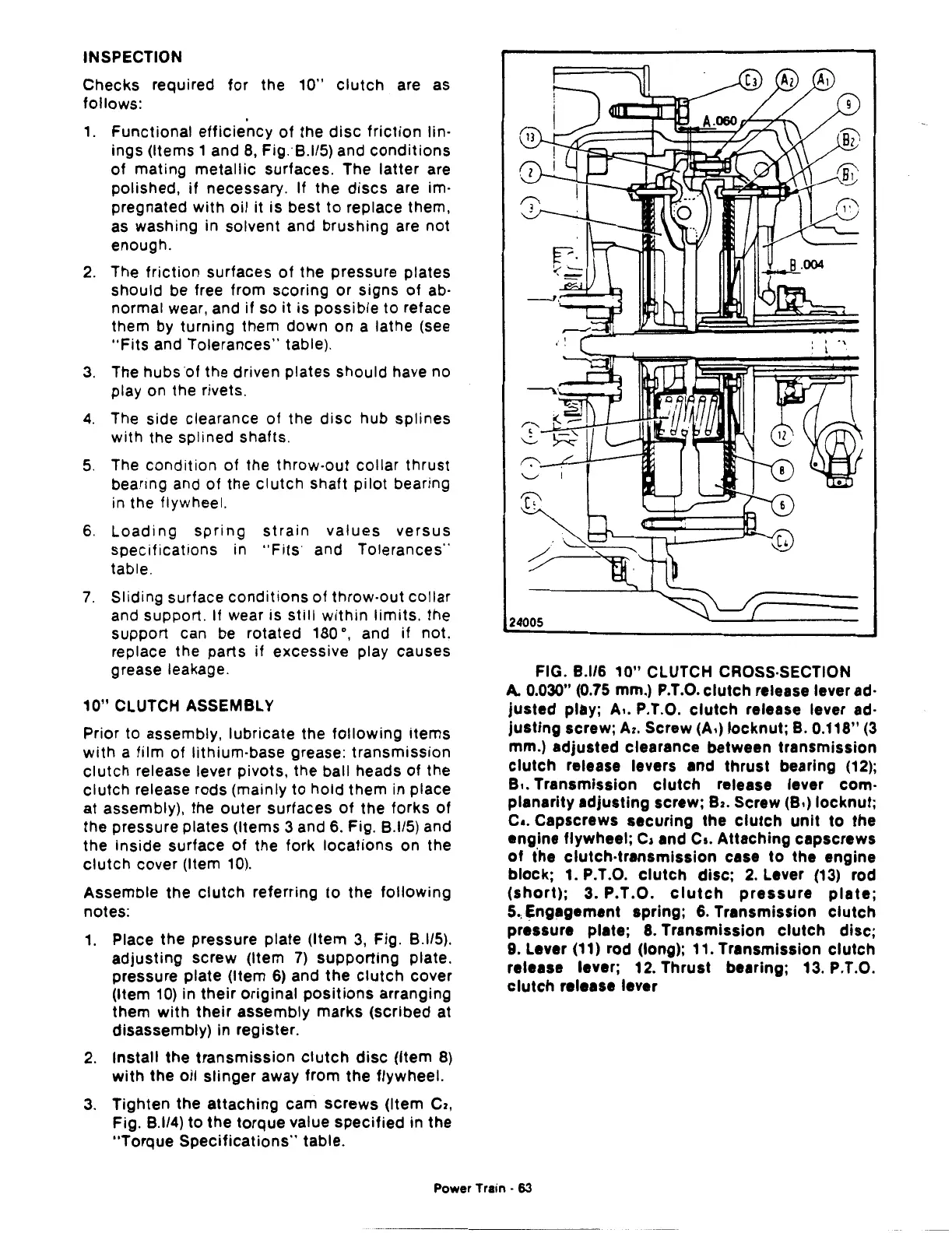
FIG.
8.1/6
10"
CLUTCH CROSS-SECTION
A.
0.030" (0.75 mm.)
P.T.O.
clutch release lever
ad-
justed play; A
•.
P.T.O.
clutch
release lever
ad-
justing screw;
A2.
Screw (A·) locknut;
B.
0.118"
(3
mm.) adjusted clearance between transmission
clutch
release levers and thrust bearing
(12);
B
•.
Transmission
clutch
release lever com-
planarity adjusting screw;
Bz.
Screw (8•) locknut;
c
•.
Capscrews securing the clutch unit to the
eng.ine flywheel;
c, and
Cs.
Attaching capscrews
of
the clutch·transmission case to the engine
block;
1. P.T.O.
clutch
disc;
2.
Lever (13) rod
(short);
3. P.T.O.
clutch
pressure
plate;
5.,
Engagement spring;
6.
Transmission clutch
pressure plate;
8.
Transmission clutch disc;
9.
Lever (11) rod (long); 11. Transmission clutch
release lever;
12. Thrust bearing; 13. P.T.O.
clutch
release lever
Power Train ·
63