55374
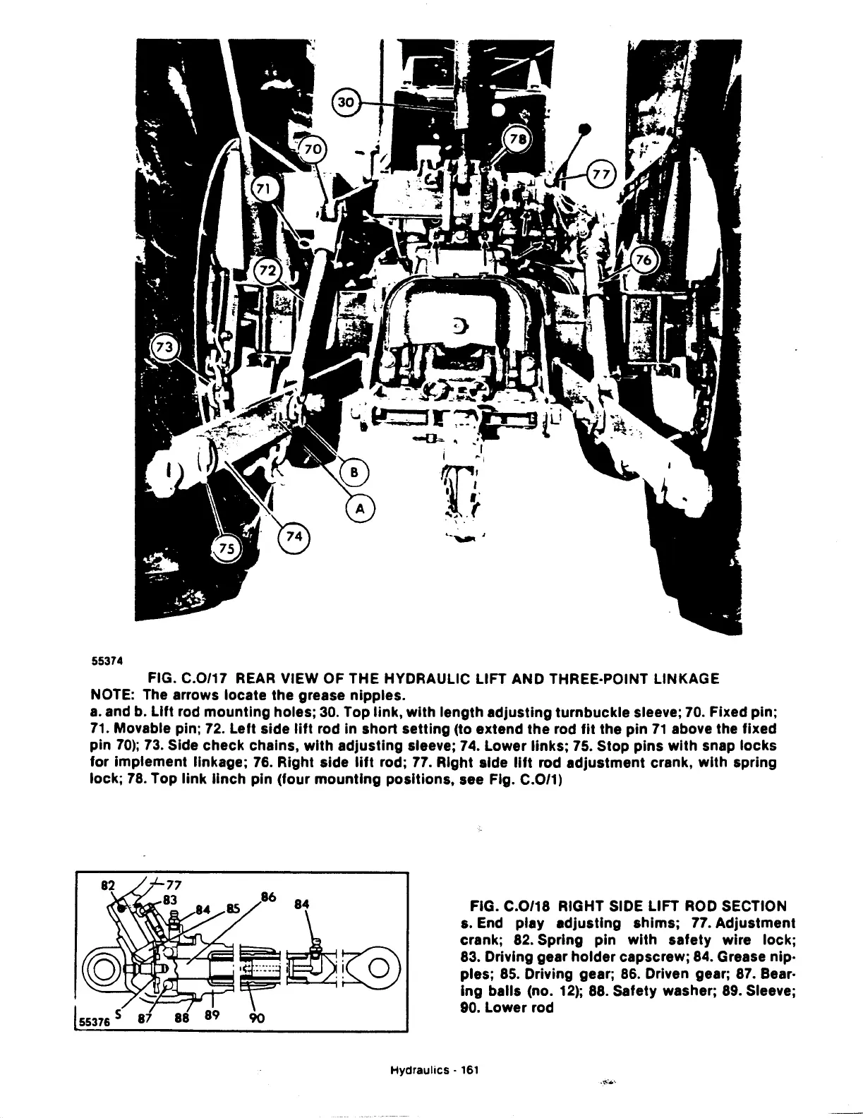
FIG. C.0/17
REAR
VIEW OF THE HYDRAULIC LIFT AND THREE·POINT LINKAGE
NOTE: The arrows locate the grease nipples.
a.
and b.
Lift
rod
mounting
holes;
30.
Top link,
with
length adjusting turnbuckle sleeve; 70. Fixed pin;
71.
Movable pin;
72.
Left side
lift
rod in short setting (to extend the rod
fit
the pin
71
above the fixed
pin
70);
73.
Side check chains,
with
adjusting sleeve; 74. Lower links; 75. Stop pins
with
snap
locks
for implement linkage;
76.
Right side
lift
rod; 77. Right side
lift
rod adjustment crank,
with
spring
lock;
78.
Top
link
linch
pin (four
mounting
positions, see Fig. C.0/1)
as
86
84
~~~.~-------·
k
-~,·
0
~r~~--~·~·······
~~
--~,y
90
FIG. C.0/18 RIGHT SIDE LIFT
ROD
SECTION
s. End play adjusting shims; 77. Adjustment
crank;
82.
Spring pin
with
safety wire lock;
83. Driving gear
holder
capscrew; 84. Grease nip·
pies;
85.
Driving gear;
86.
Driven gear;
87.
Bear·
ing
balls (no.
12);
88.
Safety washer;
89.
Sleeve;
90. Lower rod
Hydraulics
·
161
·'11'-····