B.VIII FRONT AXLE AND STEERING
DESCRIPTION
The front axle and steering
controls
for
the com-
pact, standard and vineyard
tractors
are
of
the
same basic design and
is
covered in
this
section
of
the manual.
The front wheel drive version
is
covered in a dif-
ferent section as the repair operation differ.
The steering
controls
for the above
mentioned
tractors
consist
of the
following:
Steering wheel;
Steering
column;
Steering box and
nut
shaft
with
steering arm;
Front axle assembly
with
tie
rod and
linkages.
STEERING BOX
Worm-and-nut steering box
with
1:22.4 ratio.
REMOVAL
Remove the steering box as follows:
1.
Remove
the
cowling
separating
it
from the in-
strument panel and
disconnecting
from the
latter the
lighting-starting
switch.
2.
Disconnect
the
throttle
links
from
its
leverage.
FIG. B.VIII/1 REMOVING THE STEERING ARM
(8) FROM THE STEERING BOX NUT SHAFT BY A
PULLER
c,. Steering box self·locklng screws;
Cz.
Cover
(5)
screws; 1. Drag link;
5.
Top cover
with
steer·
lng column
3.
Detach
the
drag
link
(Item
1,
Fig. B.VIII/1) or
remove the
steering
arm (Item
8)
by means of
the puller,
after
unscrewing
the nut.
4.
Remove
the
steering
box
assembly
complete
with
steering wheel
after
unscre~.-ing
the at·
taching
capscrews.
DISASSEMBLY
Before
starting
to
disassemble, drain the oil by
removing one
of
the side cover
lower
screws and
the
threaded plug,
then
proceed as follows:
1.
Remove
the
steering wheel
after
unscrewing
the nut
which
secures
it
onto
the steering
shaft.
2.
Remove
the
steering
shaft
key, remove the
screws (Item
Cz,
Fig. B.VIII/1) and then
withdraw
the cover (Item
5)
with
steering col-
umn and hand
throttle.
3.
Remove
the
capscrews
(Item
CJ.
Fig.
B.VIII/4), then
withdraw
the steering box nut
shaft
(Item
2)
and
adjuster
(Item
V),
nut
(Item
V,) and side cover (Item
9)
as an assembly,
using
a lead hammer.
4.
Withdraw
the
steering
shaft
upwards
with
worm (Item
4)
and
upper
taper roller bearing
(Item
6).
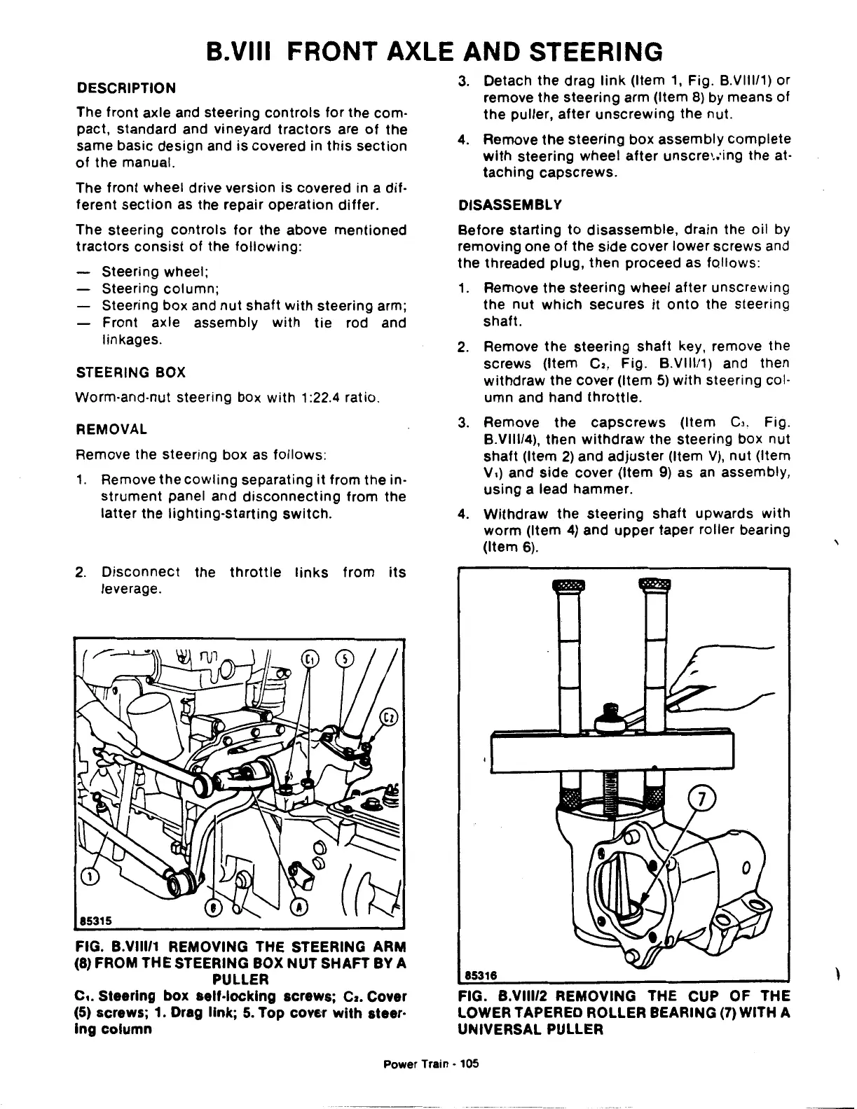
85316
FIG. B.VIII/2 REMOVING THE CUP OF THE
LOWER TAPERED ROLLER BEARING
(7)
WITH A
UNIVERSAL PULLER
Power
Train·
105
'
'