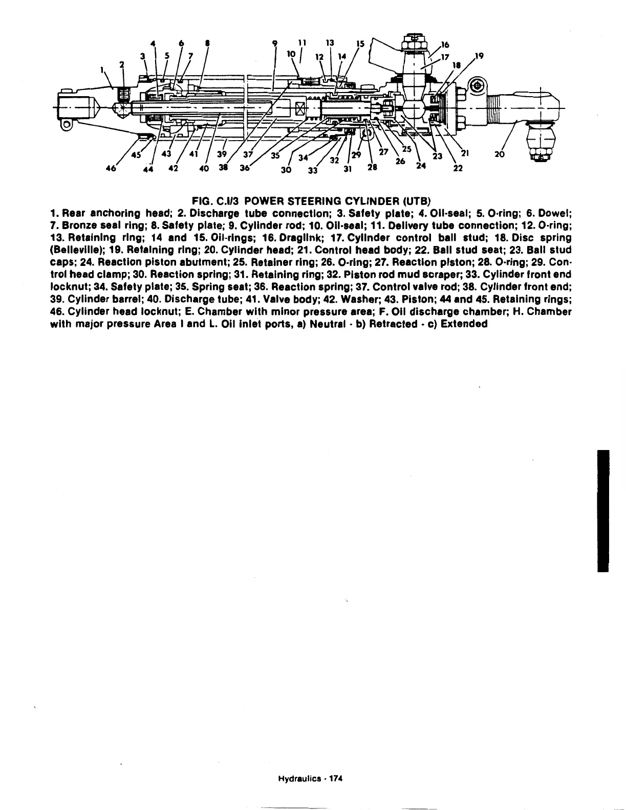
FIG. C.l/3
POWER
STEERING CYLINDER (UTB)
1. Rear anchoring head;
2.
Discharge tube connection;
3.
Safety plate; 4. Oll·seal;
5.
O·ring;
6.
Dowel;
7.
Bronze seal ring;
8.
Safety plate;
9.
Cylinder rod; 10. Oil·seal; 11. Delivery tube connection;
12.
O·ring;
13. Retaining ring; 14 and 15. Oil·rlngs; 16. Dragllnk; 17. Cylinder
control
ball stud;
18.
Disc spring
(Belleville);
19.
Retaining ring;
20.
Cylinder head;
21.
Control head body;
22.
Ball stud seat;
23.
Ball stud
caps;
24.
Reaction piston abutment;
25.
Retainer ring;
26.
O·ring;
27.
Reaction piston;
28.
O·ring;
29.
Con·
trol head clamp;
30.
Reaction spring;
31.
Retaining ring;
32.
Piston rod mud scraper;
33.
Cylinder front end
locknut;
34.
Safety plate;
35.
Spring seat;
36.
Reaction spring;
37.
Control valve rod;
38.
Cylinder front end;
39.
Cylinder barrel;
40.
Discharge tube;
41.
Valve body;
42.
Washer;
43.
Piston;
44
and 45. Retaining rings;
46. Cylinder head locknut;
E.
Chamber
with
minor pressure area;
F.
011
discharge chamber;
H.
Chamber
with
major pressure Area I and
L.
Oil Inlet ports,
a)
Neutral • b) Retracted • c) Extended
Hydraulics
• 174