c
B
A
- PRESSURE OIL
Q.-:;a
DRAIN OIL
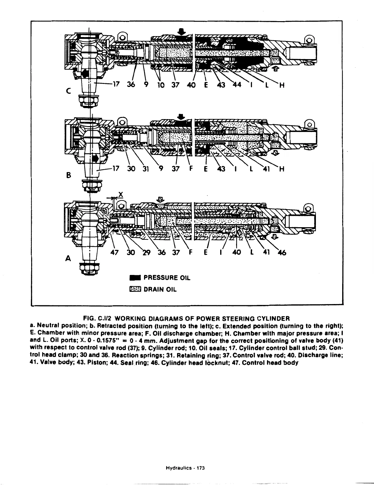
FIG. C.l/2 WORKING DIAGRAMS OF POWER STEERING CYLINDER
a.
Neutral position; b. Retracted position (turning
to
the left); c. Extended
position
(turning
to
the right);
E.
Chamber with
minor
pressure area; F.
011
discharge chamber; H. Chamber
with
major
pressure area; I
and
L.
Oil ports;
X.
0 · 0.1575" =
0.
4
mm.
Adjustment gap
for
the correct
positioning
of
valve body (41)
with
respect
to
control
valve rod
(37);
9.
Cylinder rod; 10. Oil seals; 17. Cylinder
control
ball stud; 29. Con·
trol head clamp;
30
and 36. Reaction springs; 31. Retaining ring; 37. Control valve rod; 40. Discharge line;
41. Valve body; 43. Piston; 44. Seal ring; 46. Cylinder head
locknut;
47. Control head
body
Hydraulics
· 173