- l'reaaure oil
Surtion
or
drain
nil
Static
oil
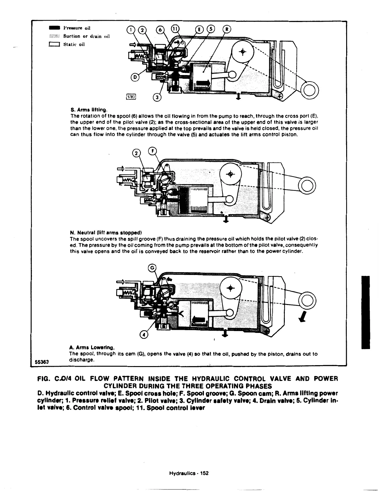
S.
Arms
lifting.
The rotation
of
the spool (6) allows the oil flowing in from the pump
to
reach, through the cross port (E),
the upper end
of
the pilot valve (2); as the cross-sectional area
of
the upper end
of
this
valve is larger
than the lower one, the pressure applied at the
top
prevails and the valve is held closed, the pressure oil
can thus
flow
into
the cylinder through the valve (5) and actuates the
lift
arms control piston.
N. Neutral (lift arms stopped)
The spool uncovers the spill groove
(F) thus draining the pressure oil which holds the
pilot
valve (2) clos·
ed. The pressure by the oil
coming
from the pump prevails at the bottom
of
the
pilot
valve, consequently
this
valve opens and the
oil
is
conveyed back
to
the reservoir rather than
to
the power cylinder.
A.
Arms Lowering.
The spool, through
its
cam
(G),
opens the valve
(4)
so that the oil, pushed by the piston, drains
out
to
55363
discharge.
FIG. C..0/4 OIL FLOW PATTERN INSIDE THE HYDRAULIC CONTROL VALVE AND POWER
CYLINDER DURING THE THREE OPERATING PHASES
D.
Hydraulic
control
valve;
E.
Spool
cross
hole; F. Spool groove; G. Spoon cam;
R.
Arms
lifting
power
cylinder; 1. Pressure relief valve; 2. Pilot valve;
3.
Cylinder safety valve;
4.
Drain valve;
5.
Cylinder In·
let
valve;
6.
Control valve spool; 11. Spool
control
lever
Hydraulics • 152