'
After
assembly, make sure that:
1.
The valves are recessed below
the
cylinder
head lower surface as specified (Fig. A.l/5).
2.
The upper spring·
cup
(Item 17, Fig. A.ll/7)
locks
(Item
18)
seat perfectly in
their
seats.
3.
Valve rod ends are
fitted
with caps (Item
19).
A CAUTION: The fuel shut-off on
this
engine is
spring loaded in the
"FUEL
ON"
position.
When turning the engine by hand,
to
adjust
valves, etc. the fuel
stop
will
have
to
be
held in
the
"OFF"
position which is
out
because under
certain
conditions
the engine could start.
VALVE GAP ADJUSTMENT
Intake:
Exhaust:
.010 in. (0.254 mm.)
.010 in. (0.254 mm.)
Adjustment
of
the gap between valves and
rocker arms can be made on engines installed or
removed from tractor, as follows:
1.
Turn the crankshaft until the first piston is at
T.D.C. at beginning
of
intake stroke and
valves are in balanced position. This position
of
piston 1 is set when the mark "P.M.S.
1"
stamped on the flywheel rim is in register
with
the pointed (Fig. A.ll/12).
2.
Turn the crankshaft one full revolution, bring·
ing the mark "P.M.S.
1"
back
to
the previous
position.
3.
Set the intake and exhaust valve gap on
cylinder 1 using the special wrench and a
feeler gauge (Fig. A.ll/10).
4.
Repeat for all remaining pairs
of
valves,
holding in mind that the stamped mark
"P.M.S.
1"
does not apply
to
pistons
2 and
3.
Consequently mark the position correspon-
ding
to
T.D.C. at intake on the flywheel with
chalk.
TAPPETS, PUSH RODS AND ROCKER ARMS
Tappets and push rods are located in the
left
side
or
crankcase. Removal
of
tappets
must
be
preceded
by
the removal
of
the camshaft and
of
the
oil
sump. Inspections and
checks
are the
following:
1.
Inspect
finish
of
surfaces contacting the
shaft
cams. Smooth
out
scoring,
if
any, with
a fine grained carborundum stone.
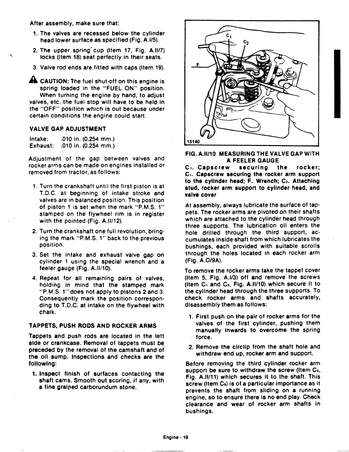
FIG. A.ll/10 MEASURING THE VALVE GAP WITH
A FEELER GAUGE
c,.
Capscrew
securing
the
rocker;
c,. Capscrew securing the rocker arm support
to
the
cylinder
head; F. Wrench;
Cz.
Attaching
stud, rocker arm support
to
cylinder head, and
valve cover
At assembly, always lubricate the surface
of
tap-
pets. The rocker arms are pivoted on their shafts
which are attached to the cylinder head through
three supports. The lubrication oil enters the
hole
drilled
through the third support, ac-
cumulates inside shaft from which lubricates the
bushings, each provided
with
suitable
scrolls
through the holes located in each rocker arm
(Fig. A.0/9A).
To remove the rocker arms take the tappet cover
(Item
5,
Fig. A.l/3)
off
and remove the screws
(Item
c,
and
Cz,
Fig. A.ll/10) which secure
it
to
the
cylinder
head through the three supports. To
check
rocker
arms and
shafts
accurately,
disassembly them as follows:
1.
First push on the pair
of
rocker arms
for
the
valves
of
the
first
cylinder, pushing them
manually Inwards
to
overcome the spring
force.
2.
Remove the
circlip
from the shaft hole and
withdraw end up, rocker arm and support.
Before removing the
third
cylinder rocker arm
support be sure
to
withdraw the screw (Item
Cs,
Fig. A.ll/11) which secures It
to
the shaft. This
screw (Item
Ca)
is
of
a particular importance as
it
prevents the shaft from sliding on a running
engine, so
to
ensure there is
no
end play. Check
clearance and wear
of
rocker arm shafts in
bushings.
Engine·
19