25345
··-~
3
Sr
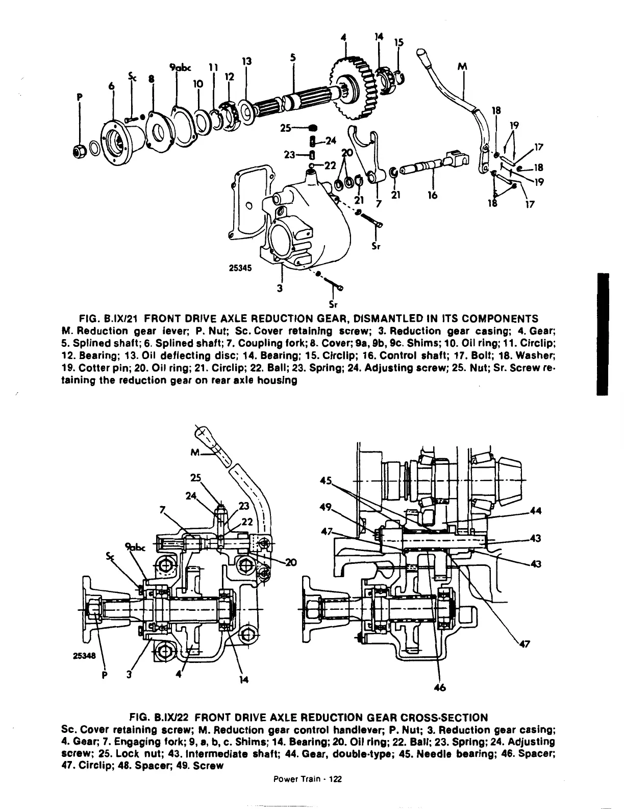
FIG. B.IX/21 FRONT DRIVE AXLE REDUCTION GEAR, DISMANTLED IN ITS COMPONENTS
M. Reduction gear lever;
P.
Nut; Sc. Cover retaining screw;
3.
Reduction gear casing;
4.
Gear;
5.
Splined shaft;
6.
Splined shaft;
7.
Coupling fork;
8.
Cover;
9a,
9b, 9c. Shims; 10. Oil ring; 11. Circlip;
12. Bearing;
13.
Oil deflecting disc; 14. Bearing; 15. Circllp; 16. Control shaft; 17. Bolt;
18.
Washer;
19. Cotter pin;
20.
Oil ring;
21.
Circlip;
22.
Ball;
23.
Spring;
24.
Adjusting screw;
25.
Nut; Sr. Screw re·
taining the reduction gear on rear axle housing
46
FIG. B.IX/22 FRONT DRIVE AXLE REDUCTION GEAR CROSS·SECTION
Sc. Cover retaining screw; M. Reduction gear control handlever;
P.
Nut;
3.
Reduction gear casing;
4.
Gear;
7.
Engaging fork;
9,
a,
b, c. Shims;
14.
Bearing;
20.
Oil ring;
22.
Ball;
23.
Spring;
24.
Adjusting
screw;
25.
Lock
nut;
43.1ntermediate shaft;
44.
Gear, double-type;
45.
Needle bearing;
46.
Spacer;
47.
Circlip;
48.
Spacer;
49.
Screw
Power Train ·
122