If
these specification requirements
of
the
cylinder safety valve cannot be met, then replace
It as separate components are not available as
spares.
The pressure relief valve can also be tested with
the hydraulic
lift
installed on the tractor, as
follows:
1.
Run the engine
to
warm the hydraulic fluid
up
to
a
temperature
of
122 °·140 •F.
(50
·-so
·c).
2.
Install a 5000
PSI
(34475
kPa)
gauge in a
remote outlet and operate the remote lever
(Item
C,
Fig. C.0/27).
3.
With the engine running at 2400
RPM
the
pressure gauge reading should read between
2133·2489
PSI
(14707-17161
kPa).
If not, ad·
just
with shims as
req1.,1ired.
Check drain valve tightness
as
follows:
1.
Place the valve and sealing rings, seat and
spring inside the adaptor
"D"
and then con-
nect the latter to a nozzle tester (Fig. C.0/26).
2.
Actuate the pump until the pressure gauge
has a reading
of
3556·4267
PSI
(24518-29420
kPa).
3.
Next, using a watch, find the time the
pressure takes to drop from 2845·1422
PSI
(19616
down to
9804
kPa).
This time should not be less than six
seconds.
If
less, first replace the sealing
rings (Item
57),
then recheck the valve
tightness.
If
the trouble persists, replace the complete
valve as
an
assembly.
REMOTE HYDRAULIC SYSTEM
The remote hydraulic system (Item
P,
Fig.
C.0/27) is used for the remote control
of
auxiliary
attachments actuated by single and double ac-
ting
hydraulic cylinders.
If
the device is used to actuate single acting
cylinders, connect a line (Item
37)
to
the lower
hole.
If It Is used
to
actuate double acting
cylinders, connect two oil lines (Item
38)
to
the
existing
holes, being sure
to
apply the adaptor
(Item
41)
In place
of
the plug (Item
36).
The holes
are tapped
for
aM
16
x 1.5 thread.
The remote hydraulic system feeds on hydraulic
lift
oil, though separately controlled through the
hand lever (Item
C,
Fig. C.0/27).
However,
the
simultaneous
operation
of
hydraulic
lift
and remote ram is not possible.
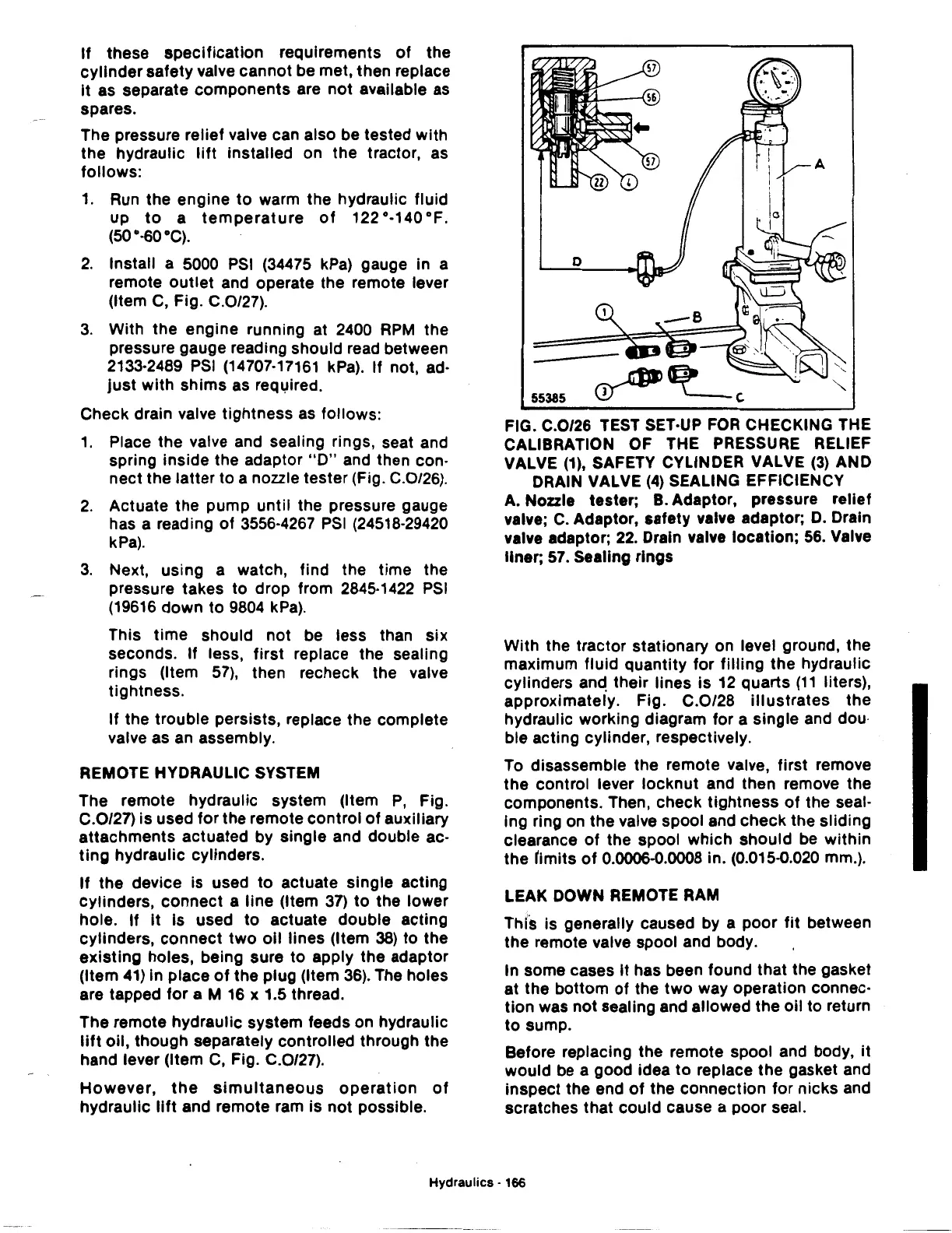
FIG. C.0/26
TEST
SET-UP
FOR
CHECKING THE
CALIBRATION OF THE
PRESSURE
RELIEF
VALVE
(1),
SAFETY CYLINDER VALVE
(3)
AND
DRAIN VALVE
(4)
SEALING EFFICIENCY
A. Nozzle tester;
B.
Adaptor, pressure relief
valve;
C.
Adaptor, safety valve adaptor;
D.
Drain
valve adaptor;
22.
Drain valve location;
56.
Valve
liner;
57.
Sealing rings
With the tractor stationary on level ground, the
maximum fluid quantity for filling the hydraulic
cylinders
an~
their lines is
12
quarts
(11
liters),
approximately. Fig. C.0/28
illustrates
the
hydraulic working diagram for a single and dou·
ble acting cylinder, respectively.
To disassemble the remote valve, first remove
the control lever locknut and then remove the
components. Then, check tightness
of
the seal-
Ing ring on the valve spool and check the sliding
clearance
of
the spool which should be within
the timits
of
0.0006-0.0008 in. (0.015-0.020 mm.).
LEAK
DOWN
REMOTE RAM
This is generally caused by a poor
fit
between
the
remote valve spool and body.
In some cases It has been found that the gasket
at the bottom
of
the
two
way operation connec-
tion was not sealing and allowed the oil to return
to
sump.
Before replacing the remote spool and body,
it
would
be
a good idea
to
replace the gasket and
inspect the end
of
the connection for nicks and
scratches that could cause a poor seal.
Hydraulics · 166