55365
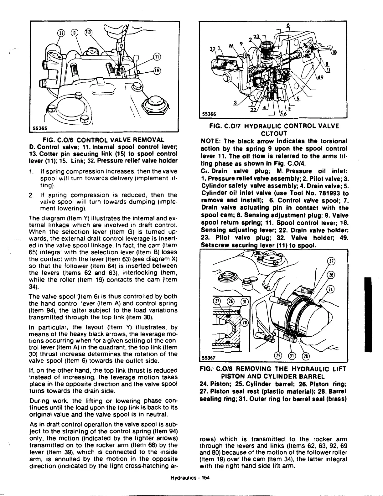
FIG. C.0/6 CONTROL VALVE REMOVAL
D.
Control valve; 11. Internal spool
control
lever;
13.
Cotter
pin securing
link
(15)
to
spool control
lever
(11
);
15.
Link;
32.
Pressure relief valve holder
1.
If
spring compression increases, then the valve
spool will turn towards delivery (implement lif·
ting).
2.
If spring compression is reduced, then the
valve spool will turn towards dumping (imple·
ment
lowering).
The diagram (Item
Y)
illustrates the internal and ex·
ternal linkage
which
are involved in draft control.
When the selection lever (Item
G)
is turned up·
wards, the external draft control leverage is insert·
ed in the valve spool linkage. In fact, the cam (Item
65)
integral
with
the selection lever (Item
B)
loses
the
contact
with
the lever (Item
63)
(see diagram
X)
so that the
follower
(Item
64)
is inserted between
the levers (Items
62
and
63),
interlocking them,
while the roller (Item
19)
contacts the cam (Item
34).
The valve spool (Item
6)
is
thus
controlled by both
the hand control lever (Item
A)
and control spring
(Item
94),
the latter subject
to
the load variations
transmitted through the
top
link (Item
30).
In particular, the layout (Item
Y)
illustrates, by
means
of
the heavy black arrows, the leverage
mo·
tions
occurring when for a given setting
of
the con-
trol lever (Item
A)
in the quadrant, the
top
link
(Item
30) thrust increase determines the rotation
of
the
valve spool (Item
6)
towards the
outlet
side.
If,
on
the
other
hand, the
top
link
thrust is reduced
instead
of
increasing, the leverage
motion
takes
place in the opposite direction and the valve spool
turns
towards the drain side.
During work, the
lifting
or
lowering phase con-
tinues
until the load upon the top link
is
back
to
its
original value and the valve spool is in neutral.
As in draft control operation the valve spool is sub-
ject
to
the straining
of
the control spring (Item
94)
only, the
motion
(indicated by the
lighter
arrows)
transmitted on
to
the rocker arm (Item
66)
by the
lever (Item
39),
which
is connected
to
the inside
arm, is annulled by the
motion
in the opposite
direction
(indicated by the
light
cross-hatching
ar-
FIG.
C.0/7
HYDRAULIC CONTROL VALVE
CUTOUT
NOTE: The
black
arrow
Indicates
the
torsional
action
by
the
spring
9
upon
the
spool
control
lever 11. The
oil
flow
is
referred
to
the
arms
lif·
tlng
phase as
shown
In Fig. C.0/4.
c
•.
Drain valve
plug;
M. Pressure
oil
inlet:
1. Pressure
relief
valve
assembly;
2.
Pilot
valve;
3.
Cylinder
safety
valve
assembly;
4.
Drain valve;
5.
Cylinder
oil
Inlet
valve (use Tool No. 781993
to
remove and Install); 6.
Control
valve
spool;
7.
Drain valve
actuating
pin
In
contact
with
the
spool
cam;
8.
Sensing
adjustment
plug;
9.
Valve
spool
return
spring;
11.
Spool
control
lever; 18.
Sensing
adjusting
lever; 22. Drain valve
holder;
23.
Pilot
valve
plug;
32. Valve
holder;
49.
lever 1)
to
s
55367
FIG.'·
C.0/8
REMOVING THE HYDRAULIC LIFT
PISTON AND CYLINDER BARREL
24.
Piston;
25.
Cylinder
barrel;
26.
Piston
ring;
27.
Piston
seal
rest
(plastic
material); 28. Barrel
sealing
ring; 31.
Outer
ring
for
barrel seal (brass)
rows) which is transmitted
to
the rocker arm
through the levers and links (Items
62, 63,
92,
69
and
80)
because
of
the
motion
of
the follower roller
(Item
19)
over the cam (Item
34),
the latter integral
with
the right hand side
lift
arm.
Hydraulics
· 154