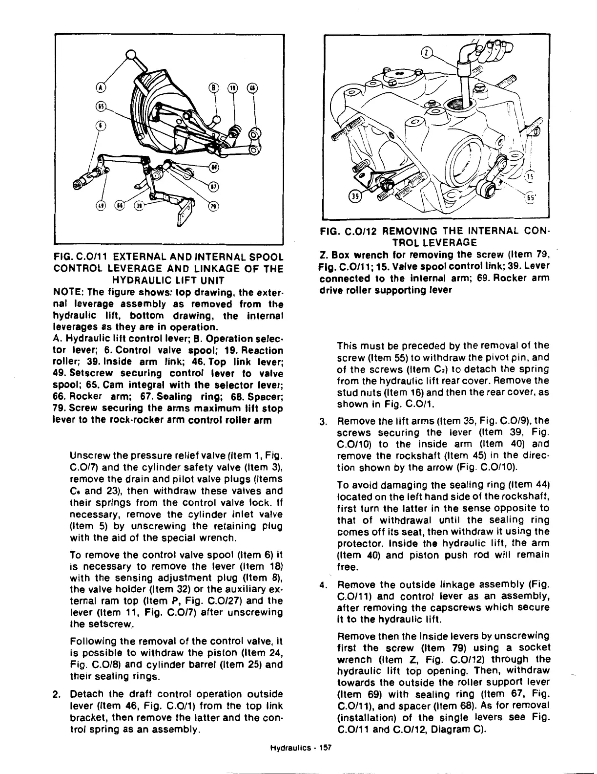
FIG. C.0/11 EXTERNAL AND INTERNAL SPOOL
CONTROL LEVERAGE AND LINKAGE OF THE
HYDRAULIC LIFT UNIT
NOTE: The figure shows:
top
drawing, the exter·
nal leverage assembly as removed from the
hydraulic
lift,
bottom
drawing, the internal
leverages as they are in operation.
A.
Hydraulic
lift
control
lever; B. Operation selec·
tor
lever; 6. Control valve spool; 19. Reaction
roller;
39.
Inside arm link;
46.
Top
link
lever;
49.
Setscrew securing
control
lever
to
valve
spool; 65. Cam integral
with
the
selector
lever;
66. Rocker arm; 67. Sealing ring; 68. Spacer;
79. Screw securing the arms maximum
lift
stop
lever to the rock-rocker arm
control
roller
arm
Unscrew the pressure relief valve (Item
1,
Fig.
C.0/7) and
the
cylinder
safety valve (Item
3),
remove the drain and
pilot
valve
plugs
(Items
Ce
and
23),
then
withdraw these valves and
their
springs from the
control
valve lock. If
necessary, remove
the
cylinder
inlet
valve
(Item
5)
by unscrewing
the
retaining plug
with
the aid
of
the special wrench.
To remove
the
control
valve spool (Item
6)
it
is necessary
to
remove
the
lever (Item
18)
with
the sensing
adjustment
plug (Item
8),
the valve
holder
(Item
32)
or
the
auxiliary ex·
ternal ram
top
(Item
P,
Fig. C.0/27) and
the
lever (Item 11, Fig. C.0/7)
after
unscrewing
the setscrew.
Following
the removal
of
the
control
valve,
it
is possible
to
withdraw
the
piston
(Item
24,
Fig. C.0/8) and
cylinder
barrel (Item
25)
and
their
sealing rings.
2.
Detach the
draft
control
operation
outside
lever (Item 46, Fig. C.0/1) from the
top
link
bracket, then remove
the
latter
and
the
con·
trol spring as an assembly.
FIG. C.0/12 REMOVING THE INTERNAL CON·
TROL LEVERAGE
Z. Box wrench for removing the screw (Item 79,
Fig. C.0/11; 15. Valve spool
control
link; 39. Lever
connected
to
the internal arm;
69.
Rocker arm
drive
roller
supporting
lever
This
must
be preceded by the removal
of
the
screw (Item
55)
to
withdraw the pivot pin, and
of
the screws (Item
C2)
to detach the spring
from the hydraulic
lift
rear cover. Remove the
stud
nuts
(Item
16)
and then the rear cover, as
shown in Fig. C.0/1.
3.
Remove
the
lift
arms (Item
35,
Fig. C.0/9), the
screws securing the lever (Item 39, Fig.
C.0/10)
to
the
inside arm (Item
40)
and
remove the rockshaft (Item
45)
in
the
direc·
tion
shown by the arrow (Fig. C.0/10).
To avoid damaging the sealing ring (Item
44)
located on the
left
hand side
of
the rockshaft,
first
turn the
latter
in the sense
opposite
to
that
of
withdrawal
until
the sealing ring
comes
off
its
seat, then withdraw it using the
protector. Inside the hydraulic
lift,
the arm
(Item
40)
and piston push rod
will
remain
free.
4.
Remove
the
outside
linkage assembly (Fig.
C.0/11) and control lever as an assembly,
after
removing
the
capscrews which secure
it
to
the
hydraulic
lift.
Remove then the inside levers by unscrewing
first
the
screw
(Item
79)
using a
socket
wrench (Item
Z,
Fig. C.0/12)
through
the
hydraulic
lift
top
opening. Then,
withdraw
towards the
outside
the roller support lever
(Item
69)
with
sealing ring (Item 67, Fig.
C.0/11), and spacer (Item
68).
As for removal
(installation)
of
the single levers see Fig.
C.0/11 and C.0/12, Diagram
C).
Hydraulics
· 157