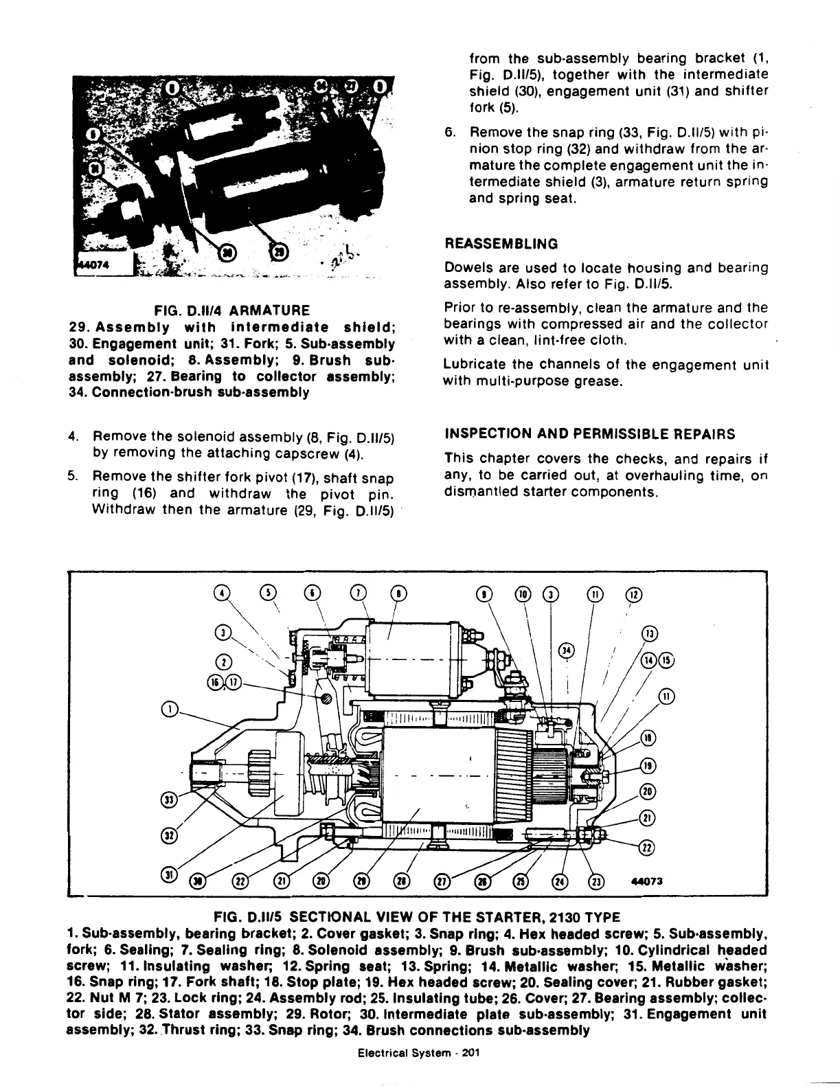
FIG.
0.11/4
ARMATURE
29.
Assembly
with
intermediate
shield;
30.
Engagement
unit;
31. Fork;
5.
Sub-assembly
and
solenoid;
8.
Assembly;
9.
Brush
sub·
assembly; 27. Bearing
to
collector
assembly;
34.
Connection-brush sub-assembly
4.
Remove the
solenoid
assembly
(8,
Fig.
0.11/5)
by removing the
attaching
capscrew
(4).
5.
Remove the
shifter
fork
pivot
(17),
shaft
snap
ring
(16)
and
withdraw
the
pivot
pin.
Withdraw
then the armature
(29,
Fig.
0.1115)
·
from the sub-assembly bearing bracket
(1,
Fig.
0.1115),
together
with
the
intermediate
shield
(30),
engagement
unit
(31)
and
shifter
fork
(5).
6.
Remove the snap ring
(33,
Fig.
0.1115)
with
pi·
nion
stop
ring
(32)
and
withdraw
from the ar·
mature the
complete
engagement
unit
the in·
termediate shield
(3),
armature return spring
and spring seat.
REASSEMBLING
Dowels are used
to
locate
housing
and bearing
assembly. Also refer
to
Fig.
0.1115.
Prior
to
re-assembly, clean the armature and the
bearings with compressed
air
and the
collector
with
a clean, lint-free cloth.
Lubricate the channels
of
the
engagement
unit
with
multi-purpose grease.
INSPECTION AND PERMISSIBLE REPAIRS
This chapter covers the checks, and repairs
if
any,
to
be carried out, at overhauling
time,
on
dismantled
starter components.
FIG.
0.1115
SECTIONAL VIEW OF THE STARTER, 2130 TYPE
1. Sub-assembly, bearing bracket;
2.
Cover gasket;
3.
Snap ring;
4.
Hex
headed screw;
5.
Sub-assembly,
fork; 6. Sealing;
7.
Sealing ring;
8.
Solenoid
assembly; 9. Brush sub-assembly; 10.
Cylindrical
headed
screw; 11.1nsulating washer; 12.
Spring
seat; 13. Spring; 14.
Metallic
washer; 15.
Metallic
washer;
16. Snap ring; 17. Fork
shaft;
18.
Stop
plate; 19.
Hex
headed screw; 20. Sealing cover; 21. Rubber gasket;
22.
Nut
M 7; 23.
Lock
ring; 24.
Assembly
rod; 25.1nsulating tube; 26. Cover; 27. Bearing assembly;
collec-
tor
side; 28.
Stator
assembly; 29. Rotor; 30. Intermediate plate sub-assembly; 31. Engagement
unit
assembly; 32 ..
Thrust
ring; 33. Snap ring; 34. Brush
connections
sub-assembly
Electrical System ·
201