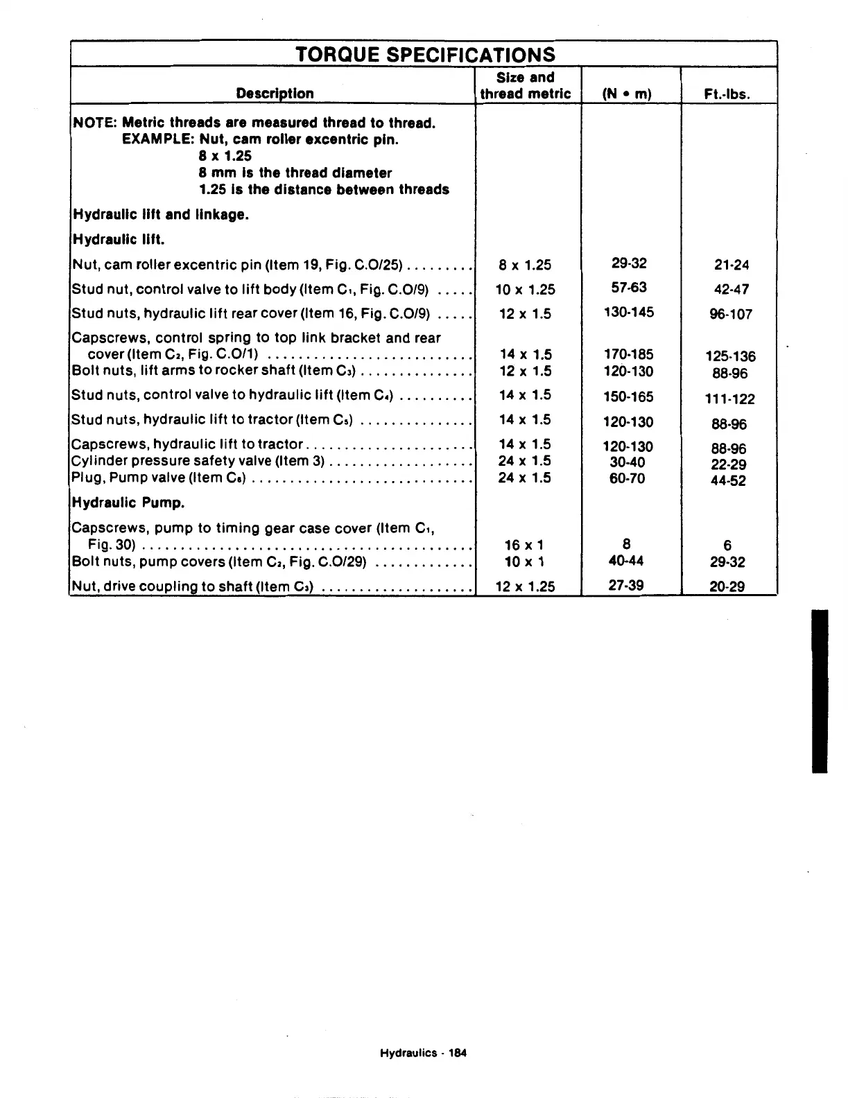
TORQUE SPECIFICATIONS
Size and
Description thread
metric
(N
• m)
Ft.-lbs.
NOTE: Metric threads are measured thread
to
thread.
EXAMPLE: Nut, cam roller excentric pin.
8
X 1.25
8
mm
Is the thread diameter
1.25 Is the distance between threads
Hydraulic
lift and linkage.
Hydraulic
lift.
Nut, cam
rollerexcentric
pin (Item
19,
Fig. C.0/25)
.........
8 X 1.25
29-32
21·24
Stud nut,
control
valve
to
lift
body (Item c,, Fig. C.0/9)
.....
10
X 1.25
57-63
42·47
Stud nuts, hydraulic
lift
rear cover (Item
16,
Fig. C.0/9)
.....
12
X 1.5
130·145
96-107
Capscrews, control spring
to
top link bracket and rear
cover (Item
C2,
Fig. C.0/1)
...........................
14
X 1.5
170·185
125-136
Bolt
nuts,
lift
arms
to
rocker shaft (Item
C3)
...............
12
X 1.5
120-130
88·96
Stud nuts, control valve
to
hydraulic
lift
(Item C.)
..........
14
X 1.5
150-165
111-122
Stud nuts, hydraulic
lift
to
tractor (Item
Cs)
...............
14
X 1.5
120·130
88·96
Capscrews, hydraulic
lift
to
tractor
......................
14
X 1.5
120·130
88·96
Cylinder pressure safety valve (Item
3)
...................
24
X 1.5
30·40
22·29
Plug, Pump valve (Item
Cs)
.............................
24
X 1.5
60·70
44-52
Hydraulic Pump.
Capscrews, pump to
timing
gear case cover (Item c,,
Fig.30)
..............................
· · · · · · · · · · · · ·
16
X 1
8
6
Bolt nuts, pump covers (Item
C2,
Fig. C.0/29)
.............
10 X 1
40-44
29·32
Nut, drive coupling
to
shaft (Item c,)
....................
12
X 1.25
27·39
20·29
Hydraulics • 184