This
voltage
should
give one
of
the
following
readings:
if
the
two
readings are null,
the
trouble
is one
specified
at
point
AS
of
the trouble-shooting
chart.
a)
greater than
15
V (high reading). The trouble
is
to
be found in the voltage regulator.
c) Less than 13.5 V (low reading).
In
this
case
also, the
two
voltage readings may give three
results:
b)
within
13.5-15 V (normal reading). In
this
case, voltage readings are necessary
to
locate
the trouble.
if
the
two
readings are about the same, the
trouble
is
to
be found in the voltage
regulator.
measure
the
voltage between terminal 85,
Fig. D.l/22a,
of
the battery charge warning
light
relay and ground.
measure the voltage between the terminal
85
of
the battery charge warning
light
relay and
the positive terminal
of
the B-terminal
of
the
alternator.
if
the
two
readings
differ
by 1 V or more, the
trouble
is
due
to
the
alternator.
if
the
two
readings give no results, the trou·
ble is that
specified
at
point
A6
of
the
trouble-shooting
chart.
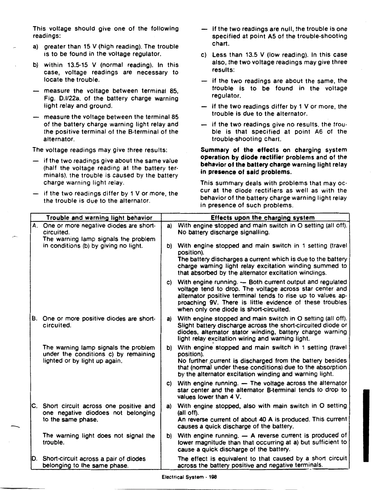
The voltage readings may give three results: Summary
of
the
effects
on charging system
operation
by
diode
rectifier
problems
and
of
the
behavior
of
the
battery
charge warning
light
relay
in
presence
of
said
problems.
A.
B.
c.
D.
if
the
two
readings give about the same value
(half the voltage reading at the battery ter·
minals), the
trouble
is caused by the battery
charge warning
light
relay.
This summary deals
with
problems
that may oc-
cur
at the
diode
rectifiers
as
well
as
with
the
behavior
of
the
battery
charge warning
light
relay
in presence
of
such problems.
if
the
two
readings
differ
by 1 V
or
more, the
the
trouble
is due
to
the alternator.
Trouble and
warnin_g
light
behavior
Effects
upon
the
charaina
system
One or more negative diodes
are
short-
a)
With engine ·stopped and main switch in 0 setting
(all
off).
circuited. No battery discharge signalling.
The warning lamp signals the problem
in conditions
(b)
by giving no light.
b)
With engine stopped and main switch in 1 setting (travel
position).
The battery discharges a current which is due to the battery
charge warning light relay excitation winding summed to
that absorbed by the alternator excitation windings.
C)
With engine running. - Both current output and regulated
voltage tend to drop. The voltage across star center and
alternator positive terminal tends
to
rise up to values
ap-
preaching
9V.
There is little evidence of these troubles
when only one diode is short-circuited.
One or more positive diodes
are
short-
a)
With engine stopped and main switch in 0 setting
(all
off).
circuited.
Slight battery discharge across the short-circuited diode or
diodes, alternator stator winding, battery charge warning
light relay excitation wiring and warning light.
'
The warning lamp signals the problem
b)
With engine stopped and main switch in 1 setting (travel
under the conditions
c)
by remaining position).
lighted or by light up again. No further
~urrent
is discharged from the battery besides
that (normal under these conditions) due
to
the absorption
by the alternator excitation winding and warning light.
C)
With engine running. - The voltage across the alternator
star center and the alternator 8-terminal tends to drop to
values lower than 4
V.
Short circuit across one positive and
a)
With engine stopped, also with main switch in 0 setting
one negative diodoes not belonging
(all off).
to
the same phase. An reverse current
of
about 40 A is produced. This current
causes a quick discharge
of
the battery.
The warning light does not signal
the
b)
With engine running. - A reverse current is produced
of
trouble.
lower magnitude than that occurring at
a)
but sufficient to
cause a quick discharge
of
the battery.
Short-circuit across a pair of diodes
The effect is equivalent
to
that caused by a short circuit
belonging
to
the same phase.
across the battery positive and negative terminals.
Electrical System • 198