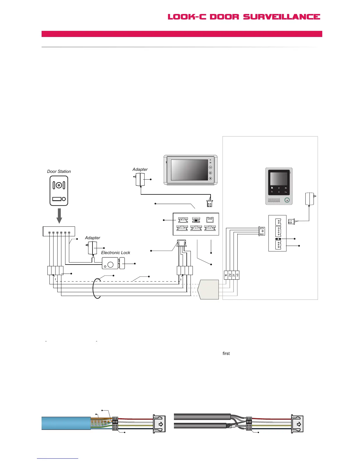
4 wires (with color Red, White, Yellow and Black) will be used to connect the Doorstation
and Monitor,
● 1R (Red): Power positive. +12V present when Door Station calling or being monitored.
● 2W (White): Power negative (Ground).
● 3Y (Yellow): Image signal (Video signal).
● 4B (Black): Talk and control signal (Audio signal).
It is recomended to use CAT5 Cable for standard installs and shielded cable for noisy installations when runing cable
with other wires (like mains cord, etc.) or steel structure buildings, industrial, etc.
[1] Power supply for the lock. This adapter is not included
in our product, please purchase the appropriate adapter
required by the electronic lock. Not required if no door lock.
[2] Relay Contact for lock control of Fail-Secure Latch.
2 Common Terminal, 1 Normally Open Terminal.
[3] Electronic Lock. See pages Lock for detailed lock
connection information, or RLC for exit button or Fail-Safety.
[4] Screw Terminal Door Station Camera
[5] RVVP cable. See Cable Pages
For simple installations with shorter cable runs use
CAT5 Twisted Pair Cable. For improved picture quality over
longer runs or in noise environments, use coax for 3Y & 2W
for detail information
[6] Shielded layer of the RVVP
Cable.
[7] JP_VD jumper. To adjust the video impedance; keep the
jumper on the last Monitor and remove all on other Monitors.
When only one Monitor installed, keep the jumper (as in this
case). Jumper on the position by default.
[8] Menu settings out-of-the-box in default are all preset for this
simplest of setup configurations. See manual for menu information.
[9] JS_OS1: Connect to
Doorstation.
[10] JS_OS2: Connect to second Doorstation / CCTV camera.
[11] JS_AP: Connect to Audio Phone (Plug compatible with H424).
[12]
If extending H427 to further H427 Monitors, connect the extra
monitor to the JS-VD connector (See multi-monitor diagram).
[13] Adapter: Power supply for the Monitor and Doorstation.
24V DC, 1000mA output.
1R
1R 2W 3Y 4B 2 1
2W
3Y
4B
1R
2W
3Y
4B
[13]
[2]
[3]
[10]
[7]
[4]
[6]
[5]
[12]
[11]
[11]
[9]
Back View
AC ~
JS/PS
JS/OS1
JVDJS/AP
P+
1R
2W
3Y
4B
2W
12V
4B
P-
TALK
H4.24 Monitor
OR
H4.27 Monitor
[7]
1
2
3
4
JS-OS1
Input 1 Input 2 Output
JS-AP
Handset 75 Ohm
Power
JP/VD DC-IN
DC- DC+
JS-OS2 JS-VD
1R
12V
2W
4B
2W
3Y
4B
1R
2W
3Y
4B
1R
2W
3Y
4B
Combine spare wires together for Power AWG
Combine All Twisted pair wires for Common Ground
Use Screw Terminals
Or Solder & Heatshrink
3Y(Yellow) Video Composite
4B(Black) Audio & Control
2W(White) Ground Common
1R(Red) Power 12Vdc
Use Screw Terminals
Or Solder & Heatshrink
3Y(Yellow) Video Composite
4B(Black) Audio & Control
2W(White) Ground Common
1R(Red) Power 12Vdc
H4.24
or
H4.27
Monitor