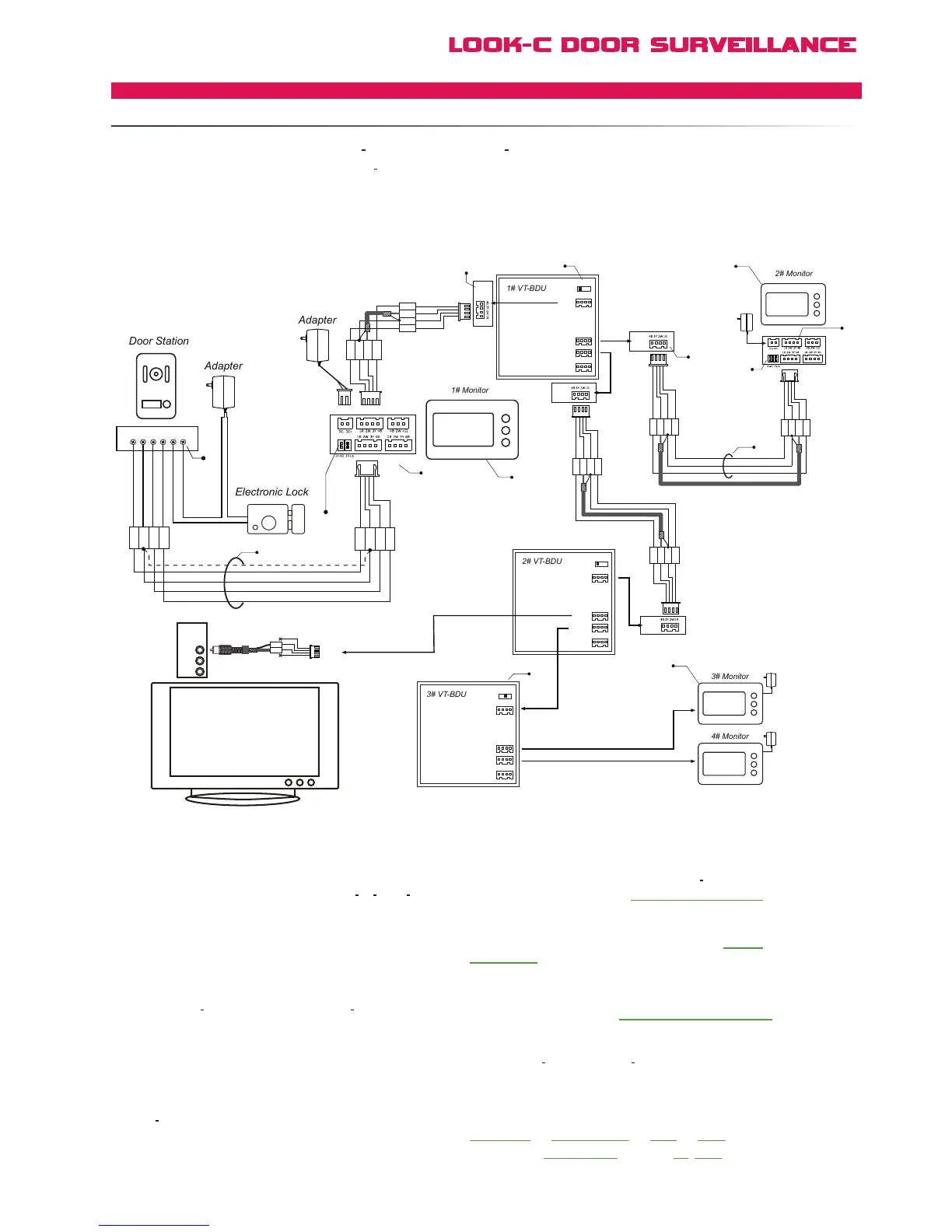
of defferent house structures. Maximum 3 VT
BDU units can be used in one system.
ConnectionDual Doorstation
[1] When the distance between two connect port is less
than 30 meters, use RVVP 4*0.5 mm
2
shielded cable, when
the distance is over 30 meters, use RVVP 75 3(RG 59)
video cable plus a RVVP 3*0.5mm
2
.
[2] Connect the Doorstation to the JW/OS port.
[3] This power adaptor is for the optional door strike only.
[4] Set the SET
3Y to HI except the last VT BDU.(4# BDU
in this case). This is the impedance setting for end-of-line 75Ω
[5]
Monitors in this topology should be all of the one same type.
See Multi-Monitor Notes. H427 shown here for connection eg. only.
[6] Each JW/VP port can be connected either Monitor or
next VT BDU unit.
[12]
“BDU Installed” Setting = “1” to enable all Monitor features.
eg. To share H427SDD Memory between extra monitors, etc.
User Setup --> Installer Setup --> 2412 --> Save -->
Select Option BDU Installed and enter “1”, Save and Exit.
[8] Multiple Monitors can be connected, and the distance
from the farest Monitor to the connected VT
BDU should be
less than 50 meters. (refer to Extend Multiple Monitors
section for connection detail).
[9] Audio phones can be extended, (refer to Extend
Audio Phone section for connection detail)
[10] Doorstation can be connected to the JS_OS2 port
of only 1# Monitor (refer to
section for connection detail).
[11] The SET
3Y of the last VT BDU must be set to 75R.
Star Topology Connection
Video Cable
Video
Audio-L
Audio-R
2W
3Y
Black
Yello
w
Red
Wh
ite
VIDEO IN
SET-3Y
JW/OS
JW/VP1
JW/VP2
JW/VP3
SET-3Y
JW/OS
JW/VP1
JW/VP2
JW/VP3
SET-3Y
JW/OS
JW/VP1
JW/VP2
JW/VP3
JS_OS1
CN101 JS_VP JS_AP
JS_OS2
1R
2W
3Y
4B
1R
2W
3Y
4B
Black
Yellow
Red
White
B
lack
Yellow
Red
Wh
i
te


 To Next Page