7
LOOK-C INSTRUCTIONS
Door Strike
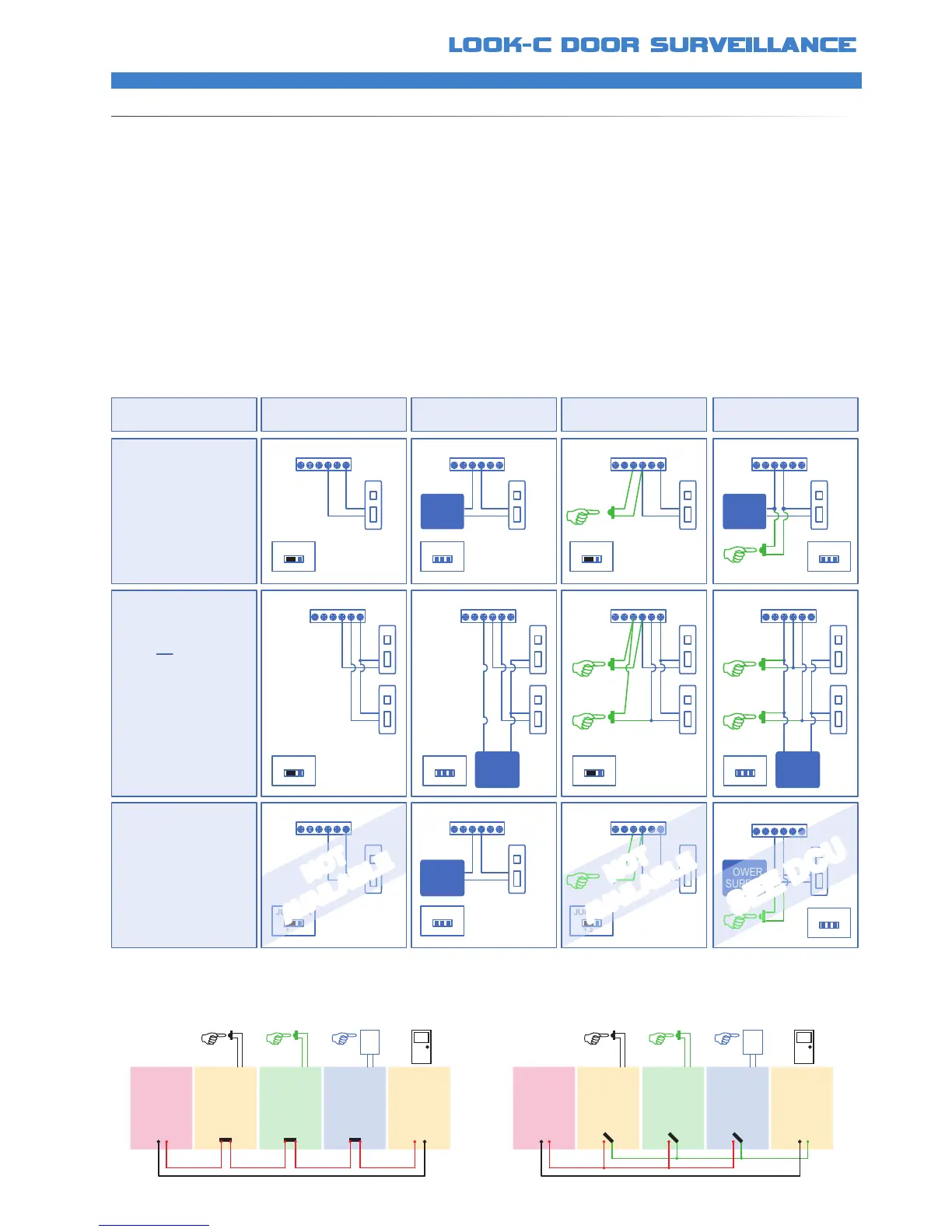
EXAMPLESOFDOORSTRIKECONNECTION
• (a) Door Camera Stations can supply power to an electronic lock of Power-On-To-Unlock type with a holding power of no more than 12V
250mA Connection cable should be less than two metres
• (b) For higher power door strikes or longer cabling, an external power source (Local) is required Connection is by dry-contact relay (NO/NC)
Removal of the “Jumper Connector” is required
• (c) The addition of an “Exit Button” is a momentary contact that triggers the door latch for door release
• (d) External Power with “Exit Button” is available
• (2a) Dual Door Strike Connection is available for controlling two door strikes Local power optional (2b)and Exit Button option (2c) or both (2d)
• (e) Power-OFF-To-Release is available and the setting programmed at the monitor Requires external power
• (f) Power-OFF-To-Release Door Strikes x2 (Optional)
• (x) Other options are available See DCU module
*Door
Strike
(a) (b) (c)
*Door
Strike
POWER
SUPPLY
BUS PL S1 S2 SCBUS PL S1 S2 SC
*Door
Strike
EXIT
Button
EXIT
Button
EXIT
Button
BUS PL S1 S2 SC
1 2 3
JUMPER
1 2 3
JUMPER
(d)
POWER
SUPPLY
BUS PL S1 S2 SC
1 2 3
JUMPER
1 2 3
JUMPER
(f)
POWER
SUPPLY
BUS PL S1 S2 SC
1 2 3
JUMPER
DOOR LATCH SECURE
Strike is set as Default
Power-On-To- Release
Note: Exit Button does
Not have actvation delay.
See DCU for time delay.
INTERNAL POWERDOOR LATCH MODE EXTERNAL POWER EXIT BUTTON (Int Pwr)
EXIT BUTTON (Ext Pwr)
BUS PL S1 S2 SC
1 2 3
JUMPER
BUS PL S1 S2 SCBUS PL S1 S2 SC
1 2 3
JUMPER
1 2 3
JUMPER
BUS PL S1 S2 SC
1 2 3
JUMPER
POWER
SUPPLY
DOOR LATCH SECURE
Strikes is set as Default
Power-On-To- Release
Two Door Strikes
POWER
SUPPLY
(x) (e) (x)
*Door
Strike
POWER
SUPPLY
BUS PL S1 S2 SCBUS PL S1 S2 SC BUS PL S1 S2 SC
1 2 3
JUMPER
1 2 3
JUMPER
1 2 3
JUMPER
DOOR LATCH SAFE
Strike can be set as
Power-Off-To- Release
This is programmed into
the door station via the
monitor menu system.
See the Instruction
Manuals for details.
(a) (b) (c) (d)
NOT
AVAILABLE
NOT
AVAILABLE
SEE DCU
Look-C 2-Wire System can control two door strikes per door station These door strikes can be powered by the door station (12Vdc @ 250mA)
or for more current or a higher voltage, you can add an external power source and use the door stations internal relay to activate the door strike
Door strikes are of two types “Fail Secure” is when power is momentarily applied to the strike to allow the door to open (Power-ON-To Release)
“Fail Safe” is when power is always on to hold the door locked, and momentarily switched off to allow the door to open (Power-OFF-To Release)
Release activation is programmed at the monitor for Fail-Secure(Default) / Fail-Safe Activation time is set from 1 to 9 seconds
Exit buttons are usually located on the inside of the premises to allow electronic door release so the person can exit the secured area
Exit buttons are not time delayed and not compatible with Fail-Safe door strikes If these features are required then see the DCU add-on
Door Bell
Button
123
456
789
0
Exit
Button
Coded
Entry
Keypad
Entry
N/C
Door
Strike
Fail-Safe
Power-OFF-To-Release
Door
Camera
N/C
Power
Supply
DCU
Exit
N/C
Door Bell
Button
123
456
789
0
Exit
Button
Coded
Entry
Keypad
Entry
N/O
Door
Strike
Fail-Secure
Power-ON-To-Release
Door
Camera
N/O
Power
Supply
DCU
Exit
N/O
• Fail-Safe / Power-OFF-To-Release type Door Strike Connections
• DCU allows a programmable Time Delay Activation for Exiting
• Shown with optional Keypad or RFID entry module
• Fail-Secure / Power-ON-To-Release type Door Strike Connections
• DCU allows a programmable Time Delay Activation for Exiting
• Shown with optional Keypad or RFID entry module