5
LOOK-C INSTRUCTIONS
2 Wire - CCTV Controller
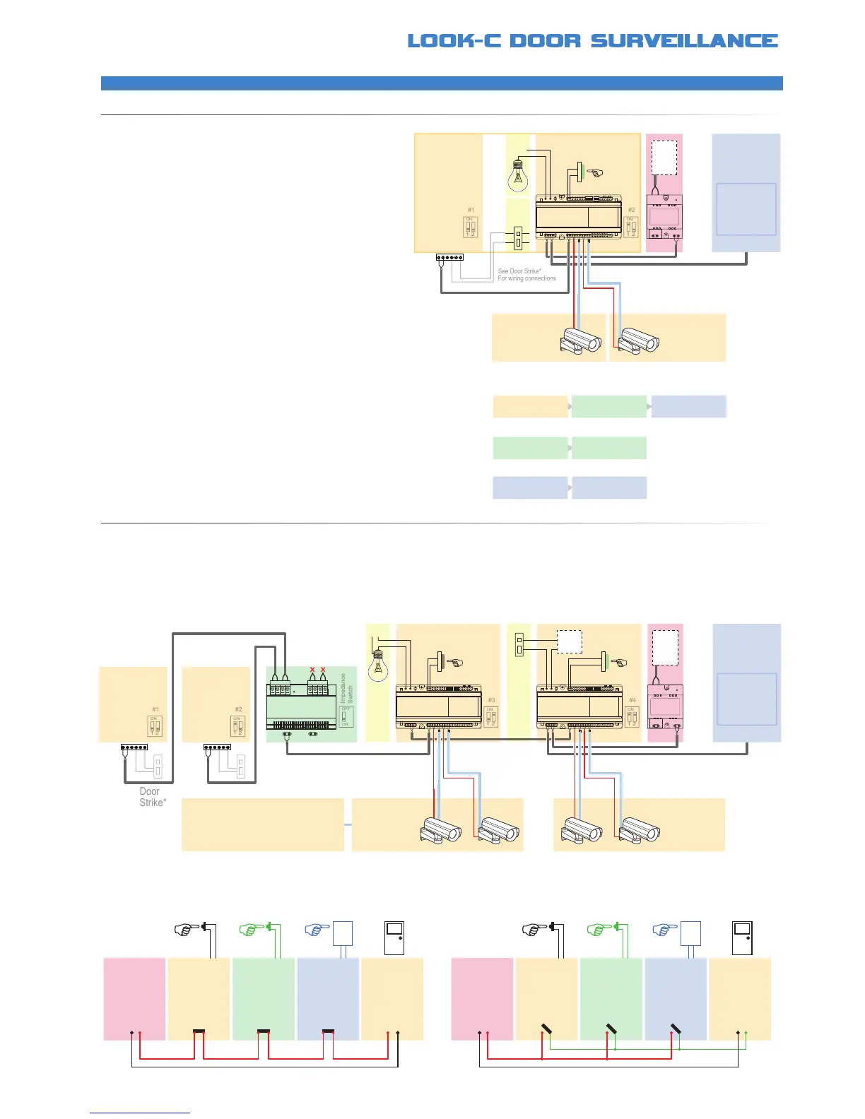
GENERALSETUPDCU
EXPANDEDSETUPDCU
Multi-function device designed to connect one or
two Standard CCTV Analogue Video Cameras into
the Look-C Two Wire Video Intercom System
Also enables a zone control point for door actuator
or Light with programmable automatic features
The diagram below shows an example of multiple DCU unit setup The DCU is identied as also the Door Cameras with a maximum of four units
Thus you can have a combination of one door station and three DCUs, or three door cameras and one DCU See manual for more information
• Connects CCTV vision into the Look-C System
• One or Two analogue video camera inputs
• Includes 12Vdc power source for the cameras
• If two cameras are connected, then on-screen
viewing is cycled between the two cameras
• Requires at least one Door Camera in system
• Connect Optional Door Actuator or a Light
DPS
1 2 3 4 5 6
ON
DCU
1 2 3 4
ON
AC
Door
Camera
#1
Door
Camera
#2a
Door
Camera
#2b
*POWER
Door
Camera
#3a & b
The Video Source can be a Camera
or other Composite Video Source.
eg. Connect to your existing DVR
Video Surveillance System, etc.
CoaxPower
Door
Camera
#4a & b
CoaxPower
• See “Examples of Door Strike Connections”
• “Exit Button” with time delay for door actuator
• Requires external power for door actuator
• Wiring connection depends on Door Strike
• DCU Contacts programmed for NO/NC*
OPTIONALDOORACTUATOR
OPTIONALLIGHTCONTROL
• or alternatively you can connect a light
• Light is triggered by push button ON with timer
or Light is toggled on/off by the push-button
or by Door Camera Station #1 call button
or by any monitor viewing the DCU
• DCU uses dry contact relay (Normally Open)
• Relay Contacts up to 240Vac 7A max
Visitor Presses
Door Bell #1
Light Switches
On
(for a preset time)
Monitor Shows
Door Camera #1
Visitor Leaving
Presses Exit Button
Door Latch Activates
for X seconds
Monitor Selects
Door Camera #2
Screen Cycles
Cameras #2a & #2b
• Door Bell Pressed on Door Camera #1 or #2 both activate the Light
• Push Button Pressed will activate/de-activate the light (toggle)
• In Auto Mode, the light will stay on for a pre-set delay, then switch off
• In manual mode, light is switched Off by the push button only (Not the Monitor)
Door Bell
Button
123
456
789
0
Exit
Button
Coded
Entry
Keypad
Entry
N/C
Door
Strike
Fail-Safe
Power-OFF-To-Release
Door
Camera
N/C
Power
Supply
DCU
Exit
N/C
Door Bell
Button
123
456
789
0
Exit
Button
Coded
Entry
Keypad
Entry
N/O
Door
Strike
Fail-Secure
Power-ON-To-Release
Door
Camera
N/O
Power
Supply
DCU
Exit
N/O
• Fail-Safe / Power-OFF-To-Release type Door Strike Connections
• DCU allows a programmable Time Delay Activation for Exiting
• Shown with optional Keypad or RFID entry module
• Fail-Secure / Power-ON-To-Release type Door Strike Connections
• DCU allows a programmable Time Delay Activation for Exiting
• Shown with optional Keypad or RFID entry module