9
LOOK-C INSTRUCTIONS
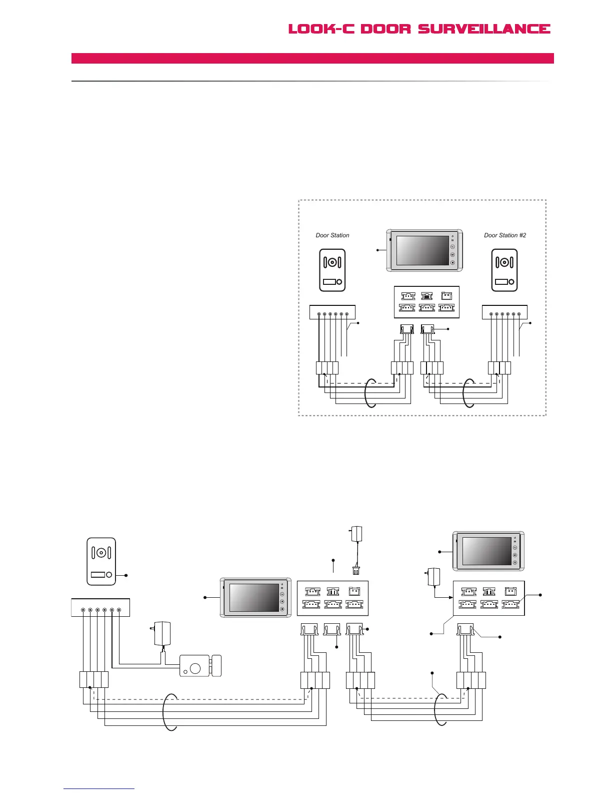
Cable length depends on cable used. See cable pages for
information. Total distance is restricted to the length between
the Door Station and the last monitor in a single chain.
Note: BDU can be used as an inline booster.
See BDU Distance Extending page for information.
[1] The 1st monitor in this chain is set to default being
Monitor #1, all subsequent monitors need to be identified
via the menu system (User Code) as monitors #2, #3, etc.
This is required for some advanced features to function.
[2] Remove the JP-VD jumper on all Monitors except the
last one. This is the 75 ohm terminator for end of line.
[3] JS-OS2 is available for a second Door Station or CCTV
Camera connection. See “Two Door Stations” for information.
[4] All the extended Monitor MUST be connected to the
JS_VP of the 1# Monitor. DO NOT connect extended
further Monitors to the JS_VP port of any other Monitor
except the 1# Monitor.
[5]
[6]
This topology is particularly suited to using the H427’s second
Video input JS-OS2. This can be a second Door Station or a CCTV
Video Camera, etc. See Two Door Stations page and the
Extend CCTV Camera page for further information.
[7]
When using 2 door stations, the 2 Way Input menu should
be set to 1 on Monitor 1#. On the Monitor Menu system,
go to User Setup > Installer Setup > 2 Way Input and
change the value from 0 to 1.
[8]
Use JS-OS1 of all extended Monitors to connect
An extra Monitor can be connected to Monitor #1 directly in this topology. When visitors call from the Doorstation, both Monitors will ring
at the same time, and either of them can answer the call, the other unit will then stop ringing. For further Monitors, a BDU module is required.
See BDU pages for Star-Wire topologies of up to four Monitors.
Audio-Only handsets can also be added to the system, see “Extend Audio Handset” page for more information.
[1]
1R
2W
3Y
4B
Electronic Lock
Adapter
Door Station
1# Monitor
+
+
-
-
AC ~
Adapter
2# Monitor
[2]
[3]
[3]
[1]
[4]
[4]
[6]
[5]
[2]
Black
Red
Black
Yellow
Red
White
1R 2W 3Y 4B 2 1
1
2
3
4
1
2
3
4
JS-OS1
Input 1 Input 2
Output
JS-AP
Handset 75 Ohm
Power
JP-VD DC-IN
DC- DC+
JS-OS2 JS-VD
1R
12V
2W
4B
2W
3Y
4B
1R
2W
3Y
4B
1R
2W
3Y
4B
JS-OS1
Input 1 Input 2
Output
JS-AP
75 Ohm
Power
JP-VD DC-IN
DC- DC+
JS-OS2 JS-VD
1R
12V
2W
4B
2W
3Y
4B
1R
2W
3Y
4B
1R
2W
3Y
4B
1R
2W
3Y
4B
Black
Yellow
Red
White
1R
2W
3Y
4B
Black
Yellow
Red
White
1R
2W
3Y
4B
Black
Yellow
Red
White
[8]
1R
1R 2W 3Y 4B 2 1
2W
3Y
4B