6
LOOK-C INSTRUCTIONS
2 Wire - Duplex
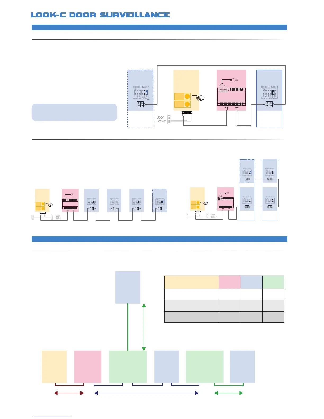
H292RHDUALBUTTONSYSTEM
H292RHMULTI-MONITORS
The H292RH Door Camera Station is a single camera with two door-bell buttons A & B Monitors are pre-set to ring on either one of the button
presses A or B The door strike is shared and monitors can intercom between each other This makes the H292RH suitable for Duplex Units with
a common door, or share situations in a common dwelling, Dual occupancy, Grannie Flats, Teenagers, Private/Ofce, Business A or B, etc
Two door strikes can be attached, however, both camera systems A & B can control both door strikes
Look-C 2-Wire System is shown here with monitors in Daisy-Chain or a
combination of Splitter and Daisy-Chain with the PS6 Power Injector The system
can be further expanded to more monitors and cameras with the DPS Power
Injector See other 2-Wire diagrams for other extended system examples
Monitor
A
Impedance DIP-6=on
Monitor #1 Button=A
1 2 3 4 5 6
ON
Impedance DIP-6=off
Monitor #17 Button=B
1 2 3 4 5 6
ON
PC6
AC~
Duplex
B
Duplex
A
• Two separated systems share a single camera
• Door Camera has two Door-Bell Buttons A or B
• Requires a minimum of two Monitors (A & B)
• DIP Switch 5 selects as Monitor for Button A or B
• Monitors control common door strike*
• Door Strike connections may vary to that shown*
• System can expand to a maximum of 16 Monitors
• Monitor at the end of a chain must be terminated
• Door Camera has two Door-Bell Buttons A or B
• DIP Switch 5 selects as Monitor for Button A or B
• Monitors control common door strike*
• Monitor at the end of a chain must be terminated
Monitor
A
Impedance DIP-6=on
Monitor #2 Cam=A
1 2 3 4 5 6
ON
Impedance DIP-6=off
Monitor #18 Cam=B
1 2 3 4 5 6
ON
Impedance DIP-6=off
Monitor #1 Cam=A
1 2 3 4 5 6
ON
Impedance DIP-6=off
Monitor #17 Cam=B
1 2 3 4 5 6
ON
PC6
BUS
DS
BUS
IM
AC~
Duplex
A
Duplex
B
Duplex
Door
Camera
A
B
Monitor
A
Power
PC6
Monitor
A
Monitor
B
Monitor
B
Impedance DIP-6=off
Monitor #2 Cam=A
1 2 3 4 5 6
ON
Impedance DIP-6=off
Monitor #1 Cam=A
1 2 3 4 5 6
ON
Impedance DIP-6=off
Monitor #17 Cam=B
1 2 3 4 5 6
ON
Impedance DIP-6=on
Monitor #18 Cam=B
1 2 3 4 5 6
ON
BUS
DS
BUS
IM
AC~
Duplex
Door
Camera
A
B
Button A rings Monitor A Button B rings Monitor B
Monitor A and B control the common door strike
Monitor A can intercom with B (and vice-versa)
PC6
Power
DBC-4S
Splitter
DBC-4S
Splitter
A
(Cam)
Monitor Monitor
B
(Master Bus)
C
(Branch)
Monitor
Door
Camera
C
(Branch)
2 Wire - Cable Information
RECOMMENDEDWIRESOLUTIONS
The maximum distance of the wiring is limited on the Look-C 2-Wire system Using different cables may also affect the maximum distance which
the system can reach The cable caries both video and data plus the power, so It is recommended that you use better quality with larger gauge
for best results over longer distances For relatively short distances, under 20 Meters, the cable choice is less critical
• Twisted pair cable is to be used
• For best Monitor Image results:
Keep runs as short as practical
Use larger gauge quality cable
• Maximum distance is approximately
100 Meters from furthest end to end
• Greater distances may be possible by
use of a DBC-4S as an in-line booster
• 24Vdc is suitable for general installs
Results may be improved with 28Vdc
• Be sure to check termination of items
at end of line (Impedance Switch)
Cable Gauge A B C
Twisted cable 2x0.75 mm
2
60M 40M 20M
Twisted cable 2x1 mm
2
70M 50M 30M
Twisted cable 2x1.5 mm
Use as a general guide only. Results may vary depending on application.
See Notes for further assistance in gaining distances and image quality.