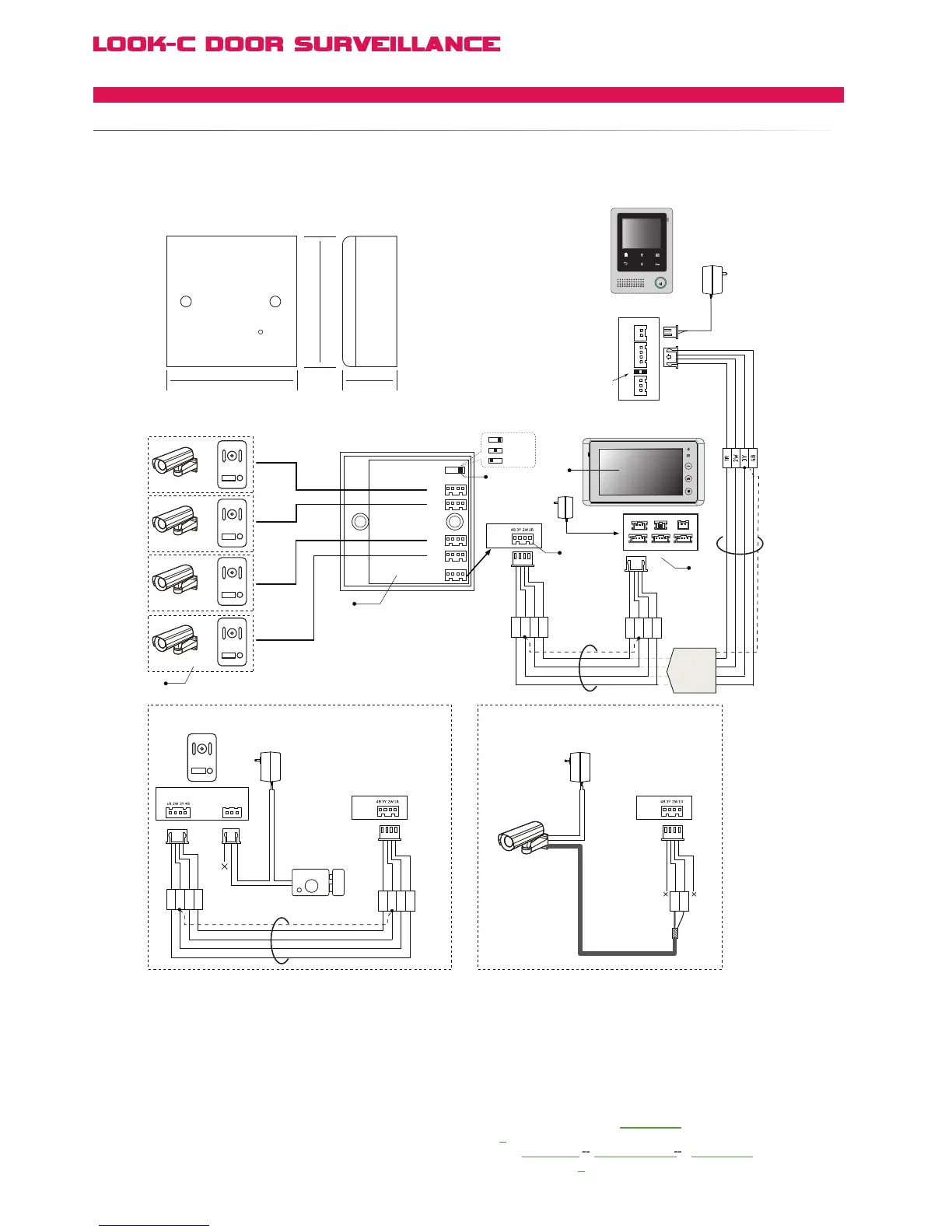
Multi-Monitor support - See Multi-Monitor Pages for connection topologies.
VT-MDS
4 Cameras Switch
IN USE
86 mm 45 mm
86 mm
DS1,2,3,4
DS1,2,3
DS1,2
3 2 1
JS_VB LB
1R
2W
3Y
4B
1R
2W
3Y
4B
VT-MDS
CCTV or Doorstation
or
or
or
N# Camera
CCTV Video Cable
Adapter
AC ~
1R
2W
3Y
4B
1R
2W
3Y
4B
N# Electronic Lock
N#
Adapter
VT-MDS
Doorstation connection CCTV Camera connection
VT-MDS
+
+
-
-
AC ~
2W
3Y
or
Black
Yellow
Red
White
Black
Yellow
Red
White
Black
Yellow
Red
White
Black
Yellow
Red
White
Black
Black
Yellow
Red
Red
White
White
SET
DS4
DS3
DS2
DS1
1#
2#
3#
4#
JW_VP
JW_VP
DS N DS N
[2]
[4]
[3]
[5]
[1]
[6]
[4]
For MDS Video Combiner, the JW-VP Video Impedance jumper
is in (Reserved) for Monitor #1 at the beguining of the chain even if
multiple monitors are used (See Multi-Monitors), JP-VP always in #1.
[5] When using MDS in the system, the H427 JS-OS2 port
becomes invalid, so DO NOT connect any Doorstation or
CCTV camera to JS-OS2 port.
[6] When using a MDS unit, the 2 Way Input menu should
be set to 0 on all the Monitors (including 1# Monitor). On the
Monitor, go to User Setup
> Installer Setup > 2 Way Input
and
change the value to 0. This is the default value.
H4.24 Monitor
Back View
AC ~
JS/PS
JS/OS1
JVDJS/AP
P+
1R
2W
3Y
4B
2W
12V
4B
P-
TALK
H4.27 Monitor
H4.24
or
H4.27
Monitor
Reserved
JS-OS1
Input 1 Input 2
Output
JS-AP
Handset 75 Ohm
Power
JP-VD DC-IN
DC-
DC+
JS-OS2 JS-VD
1R
12V
2W
4B
2W
3Y
4B
1R
2W
3Y
4B
1R
2W
3Y
4B
4 Wire - Camera Expanded
MDSMULTIDOORSTATIONSWITCH