4
LOOK-C INSTRUCTIONS
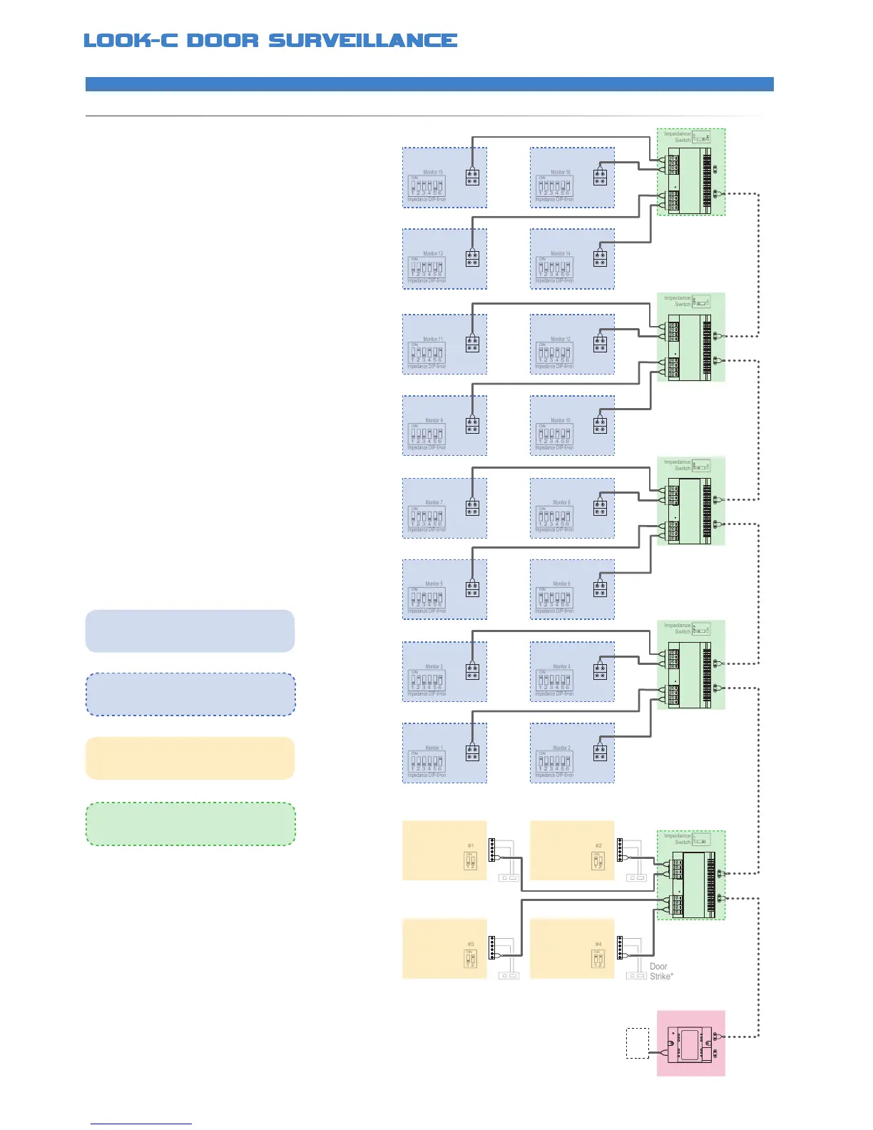
2 Wire - 4 Doors - 16 Monitors
EXPANDEDSYSTEMMAXIMUM
An example of the maximum expansion of a system
This layout demonstrates the best conguration for
low noise pictures, dependable operation with good
distance of cable runs using CAT5 or drop cable
When designing a large layout of a Look-C Door
Intercom, you can use this topology of a full system
and then remove any camera or monitor not required
The Master Bus (dotted line) is Daisy-Chain wired to
each of the DBC-4S Bus Splitters, which in turn are
Star-Wired to each unit on a branch Bus
Up to sixteen Monitors can be added to a system
This is the maximum amount of monitors identied on
a system by the monitor ID (See DIP Switches)
A maximum of four cameras can be connected to a
system with the addition of a DBC-4S Bus Splitter
Each Camera Station can control a Door strike
To power this system requires an external 24V 5 Amp
High Current Power supply and DPS Power Injector
See each units instruction manual for further details
*Further information available, see Door Strike Info
• DBC-4S Splitter for expanding to extra Monitors
• Supports up to a maximum of 16 Monitors
• Each Monitor can intercom with any other Monitor
• DBC-4S Splitter for expanding to extra Door Cameras
• Supports Two to Four Door Camera Stations
• Allows view and control of each Door Camera
• Auto switches the monitor to the appropriate camera
• Each door camera can control a door strike*
• Door Strike connections may vary to that shown*
• No Polarity, twisted pair, easily to wire solution
• Use CAT5 or twin core drop cable or equivalent
• Cable distance can be up to 100M from the Camera
• DPS Injector requires a 24V 5 Amp Power Pack
DC
24V
5A+
Monitor
DBC-4S
BUS-DS BUS-IM BUS BUS
Monitor
Monitor
Monitor
Monitor
DBC-4S
BUS BUS
Monitor
Monitor
Monitor
Monitor
DBC-4S
BUS BUS
Monitor
MonitorMonitor
Monitor
DBC-4S
BUS
Monitor
MonitorMonitor
DPS
DBC-4S
BUS BUS
Door
Camera
Multiple monitors need to be identied for the
system to operate This is done by changing
DIP Switch settings (1-16) See DIP settings
Multiple cameras need to be identied for the
system to operate This is done by changing
DIP Switch settings (1-4) See DIP settings
In this conguration, all the monitors are at the
end of each Bus so their impedance switches
need to be set to ON
The master Bus needs to be terminated at
end-of-line This is done by selecting the
DBC-4S Impedance Switch to ON