BUS
DS
BUS
IM
AC~
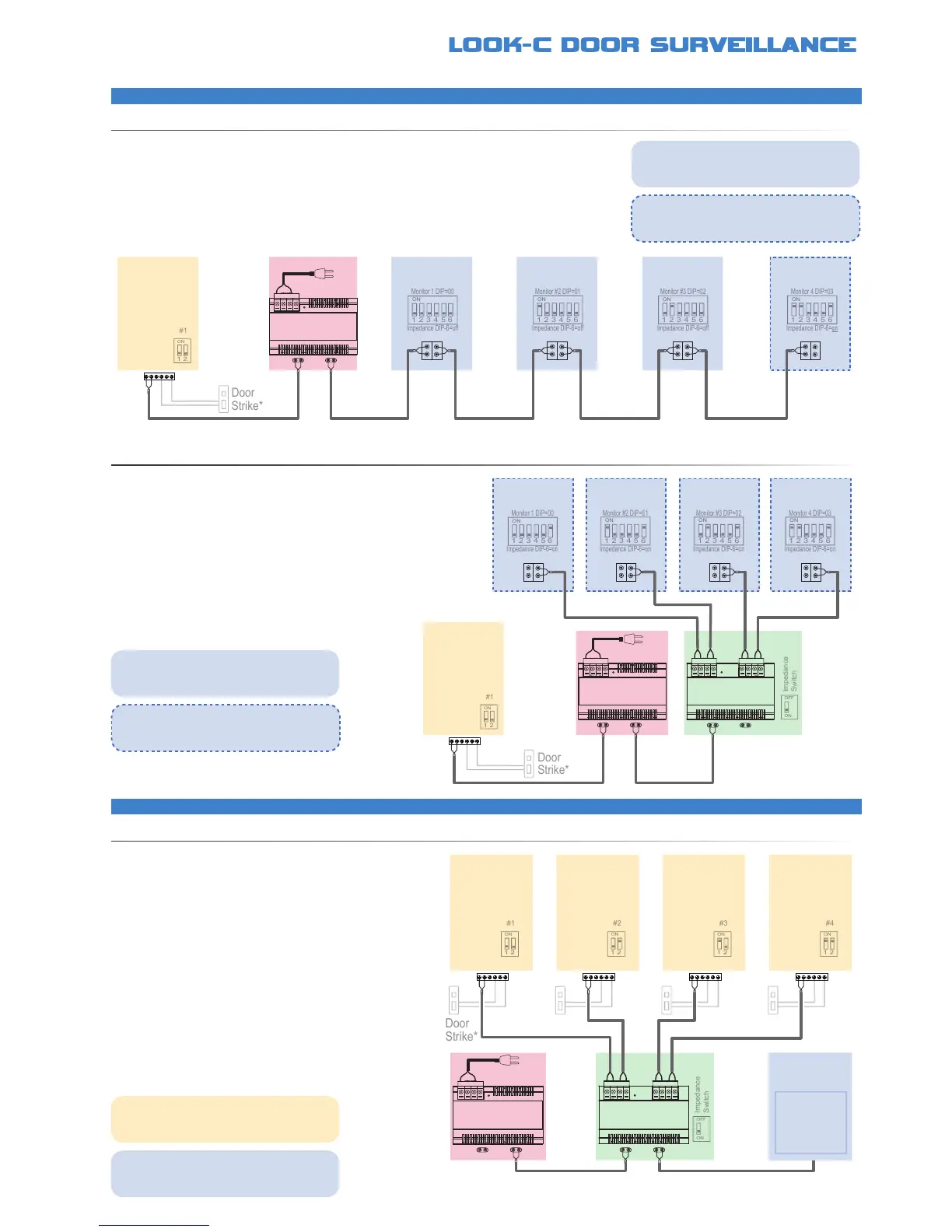
2 Wire - 1 Door - 4 Monitors
2 Wire - 4 Doors - 1 Monitor
EXPANDEDSYSTEMWITHDAISYCHAIN
EXPANDEDSYSTEMWITHSTARWIRING
EXPANDEDSYSTEMWITHSTARWIRING
System can be simply expanded to include 1 to up to 4 monitors using the existing PC6 power
solution and extending the cable in a daisy chain, up to a maximum of 100 metres cable (CAT5)
An alternative wiring system radiating from a single point by use of
the DBC-4S Bus Splitter Allows adding additional monitors, up to 4
Up to four cameras can be connected to a system with the
addition of a DBC-4S Bus Splitter Each Camera Station can
control a door by use of a Door strike PC6 Power Injector is
sufcient to run ALL Door Cameras plus up to four monitors
*Further information available, see Door Strike Info
*Further information available, see Door Strike Info
*Further information available, see Door Strike Info
• No Polarity, twisted pair, easily to wire solution Use CAT5 or twin core drop cable or equivalent
• Cable distance can be up to 100M total when using CAT5 cable (from camera to last monitor)
• One common power supply to all type solution (Use PC6 Mains Power or DPS Power Injector)
• Connect multiple monitors from 2 to 4 on the one Bus with PC6 Power and a Door Camera
• Monitor DIP Switches need setting Monitor Menu needs setting for Master/Slave (See manual)
• DBC-4S Splitter for a Star Wiring alternative
• No Polarity, twisted pair, easily to wire solution
• Use CAT5 or twin core drop cable or equivalent
• Cable distance can be up to 100M when using CAT5 cable
from the Door Camera to the furthest of the monitors
• One common power supply to all type solution (PC6 or DPS)
• Monitor DIP Switches need setting Monitor Menu needs
setting for Master/Slave (See Monitor Instruction Manual)
• DBC-4S Splitter for expanding to extra Door Cameras
• DBC-4S Supports Two to Four Door Camera Stations
• Allows view and control of each Door Camera & Door strike
• Auto switches the monitor to the appropriate camera
• Cameras are internally terminated, so no Impedance switch
to set and Daisy-chain wiring is not available for cameras
• Cable distance can be up to 100M from Camera to Monitor
• PC6 has enough power to supply more Monitors
in a further expanded system (See above)
†
• Each door camera can control a door strike*
• Door Strike connections may vary to that shown*
Door
Camera
Monitor
BUS
DS
BUS
IM
Single or
Multiple
Monitors
Multiple monitors need to be identied for the
system to operate This is done by changing
DIP Switch settings (1-16) See DIP settings
Multiple monitors need to be identied for the
system to operate This is done by changing
DIP Switch settings (1-16) See DIP settings
Multiple cameras need to be identied for the
system to operate This is done by changing
DIP Switch settings (1-4) See DIP settings
In this conguration, all monitors impedance
switches need to be set to OFF, except the
end (last) monitor’s impedance is set to ON
In this conguration, all the monitors are at the
end of each Bus so their impedance switches
need to be set to ON
In this conguration, only one monitor is shown
Further monitors can be added, see multi-
monitor congurations for further information